From LCD to LED Displays: The Technical Custom Digital Clock Buyer’s Guide for Consumer Tech Brands
The Physics of Clock Drift: Why Premium Smart Devices Lose Minutes Under Thermal Stress

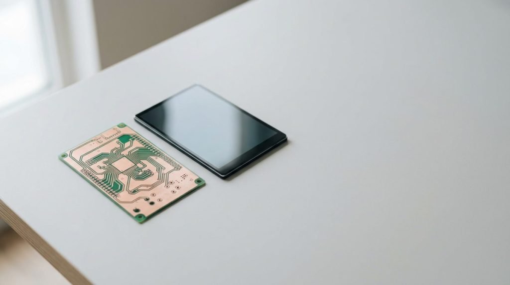
Optimal PCB routing isolates the timing crystal from active thermal zones to prevent drift.
Timing accuracy is almost never a component-cost problem; it is a thermal routing problem. While procurement teams often focus on sourcing a 10 PPM quartz crystal to guarantee precision, a poor board layout will ruin its performance within weeks of field deployment. This engineering oversight is why high-end smart ovens, connected thermostats, and industrial displays frequently lose multiple minutes over a single season. The physics of uncompensated tuning-fork quartz crystals are unforgiving. Standard oscillators are calibrated for a stable 25°C factory environment, but they operate on a parabolic temperature curve. If internal temperatures shift by just 15°C, the uncompensated crystal can drift by up to 20 seconds per month—gradually eroding consumer trust in a premium appliance.
The issue is driven by display thermal traps inherent in modern, compact, sealed plastic housings. These tight enclosures act as heat sinks in reverse, concentrating heat from Wi-Fi modules, power regulators, and backlights directly onto the timing board. This makes the B2B buyer’s core optical choice highly critical: opting for high-intensity active LED modules instead of low-power passive segmented LCD panels changes the entire internal thermal profile. While a passive segmented LCD runs cool, an active LED module acts as a continuous heat radiator. To prevent this, custom ODM manufacturing partners like YGhao isolate the clock on the PCB. During QA testing, when we stress thermal limits, uncompensated crystals fail without physical intervention. Engineers must design dedicated keep-out zones and milled ground-plane isolation slots on custom clock PCBs to decouple the oscillator from active heat pathways.
Reviewing the layout on the first Gerber file submission prevents expensive tooling changes later. When auditing an OEM’s board, verify a minimum 10mm physical isolation gap or a milled thermal isolation slot between the timing crystal and any high-current traces; if the layout lacks this physical barrier, the clock will drift no matter how premium the crystal on the datasheet.
Custom LCD vs. Segment LED: Specifying Waveforms, Voltages, and Tooling Costs
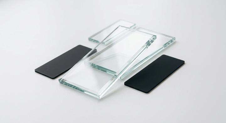
Choosing the right display substrate impacts both tooling economics and operating thermal limits.
Is a custom segmented LCD glass mold cheaper in bulk runs than off-the-shelf LED display modules?
For product development teams, estimating the initial tooling costs is the main hurdle before production can scale, particularly when comparing the $800 to $1,500 tooling for LED modules against the upfront cost of custom glass. When designing a custom digital clock, opting for a Twisted Nematic or High Twisted Nematic glass display shields your system from localized heat, though you must drive these LCD substrates with complex alternating current (AC) waveforms to prevent electrochemical breakdown of the fluid.
| Display Substrate Type | Driving Voltage (V) & Average Drive Current (mA) | Relative Tooling Cost | Optimal Operating Temperature Bounds | Sourcing Fit, Primary Risks & Verdict |
|---|---|---|---|---|
| TN LCD (Twisted Nematic) | 3.0V – 5.0V (AC) 0.005 – 0.015 mA | Low ($1,200 – $1,800) | 0°C to +50°C | Fit: Indoor appliances. Risks: Limited off-axis viewing; ghosting. Verdict: Lowest per-unit cost above 10k runs. |
| HTN LCD (High Twisted Nematic) | 3.0V – 5.0V (AC) 0.010 – 0.020 mA | Moderate ($1,500 – $2,000) | -10°C to +60°C | Fit: Handheld tools and basic meters. Risks: Contrast drops at off-axis angles under high multiplexing. Verdict: Good viewing sweep upgrade over basic TN. |
| FSTN LCD (Film-compensated) | 3.3V – 5.0V (AC) 0.015 – 0.030 mA | High ($2,000 – $2,500) | -20°C to +70°C | Fit: Outdoor instruments needing daylight contrast. Risks: Sluggish segment response times at extreme sub-zero temperatures. Verdict: Highest passive readability under direct sun. |
| Segment LED Module | 1.8V – 3.3V (DC) 10.0 – 50.0 mA | Low-Mod ($800 – $1,500) | -40°C to +85°C | Fit: Mains-powered dark-room displays. Risks: Continuous current draw drives local thermal drift in timing circuits. Verdict: High brightness and widest operating thermal limits. |
Sourcing Verdict: Substrate Selection and Tooling Economics
For high-volume consumer products, the lower unit cost of TN or HTN glass quickly amortizes the initial non-recurring engineering (NRE) fees. While a custom digital clock built with FSTN glass demands a steeper initial investment of $2,000 to $2,500, it remains the only viable passive option for outdoor applications where direct daylight washes out standard segment LEDs. When validating these display assemblies, we run environmental chamber tests across key thermal points—specifically checking response times and liquid crystal stability at 0°C, 10°C, 20°C, 40°C, 50°C, 60°C, 70°C, and 85°C—to ensure the display won’t drop contrast or experience ghosting in real-world environments.
Application Blueprints: Component Selections for Home Appliances, Handhelds, and Terminals
The thermal imaging camera at the 7:00 AM calibration shift shows a bright red bloom right where the oscillator sits next to the power supply. While raw display waveforms look clean on an open test bench, mounting these systems into sealed product housings introduces localized heat pockets, strict battery budgets, and outdoor glare that will degrade both timing and readability. Transitioning from a theoretical schematic to a reliable, long-term custom digital clock module requires matching the crystal grade and display glass to the physical reality of the enclosure itself.
Kitchen Appliances and Heat Enclosures For Ovens
When sourcing displays for high-heat kitchen appliances, the bill of materials must withstand internal ambient temperatures climbing past 85°C. Standard commercial quartz crystals drift rapidly under these conditions, turning an oven clock into a warranty liability within six months. For these tight heat enclosures for built-in ranges and home appliances, we specify high-intensity LED segments mounted on a 105°C rated high-Tg glass-epoxy PCB. The layout must isolate the timing source by using a shielded TCXO positioned in the absolute coolest corner of the board, far from the mains transformer and high-current relays. At YGhao, we run thermal simulations on the Gerber files before tooling the casing because moving a component 15mm to the left is free, while re-spinning a production-run board after molding is an expensive disaster.
Powered Smart Home Devices and Power Constraints
Battery-operated hardware represents the opposite engineering hurdle, where micro-amp consumption dictates market viability rather than raw thermal load. For powered smart home devices, a high-draw active oscillator or an active LED segment will drain standard AA cells in under ninety days. A pragmatic layout uses a custom-cut reflective FSTN display—requiring zero backlight current in daytime ambient light—paired with a standard 20 PPM tuning-fork crystal. By routing the clock signal through a dedicated micro-amp sleep controller, the main MCU remains in deep standby, waking for mere milliseconds to refresh the display drive waveforms. We test these assemblies at 20°C to verify baseline current leakage because even a single micro-amp of parasitic draw will ruin your three-year battery life target.
PCB and Enclosure Sinks: Engineering Pitfalls That Ruin High-Volume Runs
Before a custom digital clock project moves to high-volume runs, mechanical layout requirements must be locked down to prevent line defects. While a schematic simulates perfectly, physical manufacturing variables on the assembly line will destroy timing accuracy. Translating a clock design into mass production requires protecting sensitive timing circuitry from the physical stresses of SMT assembly, static buildup, and housing contraction.
Standard lead-free reflow profiles are safe for any SMD crystal.
A typical SAC305 profile peaking at 260°C frequently exceeds the glass-to-metal seal limits of sub-miniature 32.768 kHz crystals. This thermal shock creates microscopic package fractures, inviting moisture ingress over months of deployment in humid environments. SMT line profiles must be calibrated for the specific crystal, keeping peak reflow exposure under 245°C or utilizing a specialized low-temperature alloy to protect the hermetic seal.
Plastic display bezels act as natural insulators that protect the clock from static.
In dry environments, plastic bezels act as static collectors rather than shields. Up to 15kV of electrostatic discharge can creep through the bezel gap, arcing into the LCD’s indium tin oxide electrodes and traveling down driver traces to lock up the microcontroller. At YGhao, we mitigate this by routing a continuous copper ground trace around the display perimeter on the PCB, shunting static safely to the chassis ground before it corrupts sensitive oscillator pins.
Nominal CAD dimensions are a safe baseline for plastic enclosure tooling.
Ignoring polymer contraction will warp alignments or crack display glass. ABS shrinks by 0.4% to 0.7%, whereas polycarbonate contracts by up to 0.8% depending on wall thickness and mold cooling. Relying on nominal CAD dimensions without calculating tolerance stack-ups can cause a shrinking bezel to pinch the display glass in cold transit. This localized pressure shifts liquid crystal polarization, creating permanent dark spots, or cracks the panel under thermal transitions.
High-speed signal lines are safe near the crystal as long as ground copper is between them.
Ground shielding cannot overcome parasitic capacitive coupling near high-impedance nodes. Running high-frequency signal traces directly underneath or adjacent to sensitive 32.768 kHz crystal pins couples digital noise into the feedback loop. This parasitic coupling shifts the switching threshold of the MCU’s internal inverter, causing clock drift. The layout must isolate the timing loop within a guard ring, keeping active traces clear of the crystal footprint.
Has your supplier actually verified their SMT reflow profile against your crystal’s thermal limit?
The Supplier Audit Checklist: SMT Quality Gates and Display Burn-In Standards
What technical evidence proves a display factory can reliably assemble a custom digital clock without thermal drift or pixel failures?
Paper certificates like ISO 9001 are easy to print, but they do not prevent cold solder joints or crystal micro-fractures during high-temperature reflow. To ensure long-term stability in the field, a procurement team must look past the paperwork and audit the factory floor with a rigorous hardware checklist. This audit should focus directly on SMT quality gates, specialized environmental test chambers, and active display aging lines.
The table below outlines the core audit checkpoints that separate reliable ODM partners from low-tier assemblers.
| Ask | Expected Evidence | Red Flag | Responsible Party |
|---|---|---|---|
| AOI Solder Joint Validation | 100% automated optical inspection (AOI) records confirming the supplier checks lead-free solder joint shapes on tiny SMD crystal packages down to 2.0×1.2mm footprints. | Hand-soldered crystals or manual magnifying-glass inspection for critical timing components. | Factory SMT Line Supervisor |
| Environmental Bias (THB) | Long-term thermal-humidity bias (THB) chamber logs showing random batch samples run under continuous load at high heat/humidity to reveal trace liquid crystal leaks. | “Weather testing” certificates that lack active electrical bias data or are older than 12 months. | QA / Reliability Lab Manager |
| Segment Illumination Burn-In | 100% of finished display modules running continuously at maximum load for 24 to 72 hours on active aging racks to weed out early infant mortality in LEDs or LCD segments. | Spot-checking only 5% of the batch, or reducing the aging cycle to under 12 hours to speed up shipments. | Outgoing Quality Control (OQC) |
When walking the line, pay close attention to the SMT reflow profile logs. Real-world quality is won or lost in the thermal zoning of the reflow oven. If a factory runs a generic profile for boards containing both heavy LCD pins and tiny, heat-sensitive quartz crystals, the crystals will suffer. Overheating a crystal package during the reflow process can warp its internal copper spring or degrade the hermetic seal. This damage causes a slow gas leak that allows moisture to creep in, resulting in a severe clock drift that only reveals itself three months after the finished custom digital clock has reached the consumer.
A quality-focused supplier will actively track solder paste height using 3D Solder Paste Inspection (SPI) before components ever reach the mounter, protecting the integrity of tiny SMD pads. If a factory claims their SMT line is “fully automated” but cannot show you live SPI feedback or their weekly oven-zone calibration logs, it usually means the machinery is running unmonitored.
If you are preparing an RFQ or need to compare engineering standards, contact the technical team at YGhao. We can provide standard reflow profiles, thermal-humidity bias logs, and complete DFM review templates to help align your design with reliable mass production gates.
Tooling Timelines and DFM Hand-Offs: Initiating Custom Clock Production
Once your environmental validation parameters are locked and you have decided between a custom segmented LCD and a segment LED, the next step is physical integration. Initiating custom clock production relies on a clean Design for Manufacturability (DFM) review to align your mechanical housing with our board layout. Exchanging 3D STEP files of your device enclosure and display bezel early is the only real way to check clearance lines and prevent assembly misalignment. A physical variance of just 0.2 mm is enough to pinch an LCD polarizer, warp a light guide, or let backlight bleed ruin your front panel aesthetics. Once those mechanical boundaries are validated and your vector artwork is signed off, the clock starts on physical tooling timelines. Producing custom glass masks or milling the injection molds for backlight diffusers typically takes 14 to 21 days from artwork approval to the first functional prototype sample.
Integrating these physical constraints with electrical stability requires a partner that can support custom segment layouts, integrated backlight diffusers, and custom MCU firmware programming simultaneously. YGhao handles this validation before any tool steel is cut, preventing the display footprint and driver mismatches that typically delay product launches by weeks. To keep your development on track, your engineering team can download our standard driver circuit layouts and footprint templates, or upload your physical housing drawings to our engineering desk for a comprehensive DFM review.