Custom Digital Clock Prototypes: How to Fast-Track Low-Volume NPI Projects with YGhao
The Board-Fit Trap: Why Off-the-Shelf PCBA Modules Break Custom Clock Designs
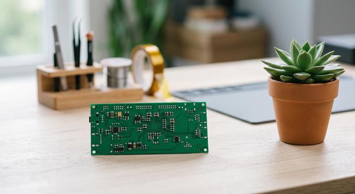
A clean hardware engineering environment where custom PCBA layouts are validated before SMT runs.
Physical housing conflicts, not electronics, are what kill a custom digital clock project on the assembly line. Many procurement teams try to dodge upfront engineering fees by dropping standard, pre-made PCBA boards into custom-designed enclosures. On the factory floor, this shortcut falls apart: off-the-shelf clock modules leave ugly, uneven gaps around custom display bezels or smash directly into the internal mounting bosses meant to secure the housing. Worse, sealing a cheap 32.768 kHz tuning-fork crystal inside a warm, unvented custom enclosure causes rapid thermal clock drift. Because these low-cost crystals are calibrated for a steady 25°C, the ambient heat trapped from driving the display and microcontrollers forces the clock to lose minutes every month once it reaches the end user.
This structural oversight is usually driven by a hard manufacturing gap in South China, where Massive Tier Electronic Manufacturing Services providers reject any assembly runs under 10,000 units. For brands stuck in this middle ground, relying on generic components feels like the only viable path to avoid massive tooling lock-in. We built YGhao to bridge this gap, acting as a dedicated NPI partner that handles short runs from 100 to 5,000 units. By designing a custom PCBA tailored to your physical housing from day one, you get clean cosmetic integration without the financial risk of high-volume commitments.
Avoiding these tooling headaches comes down to a simple, non-negotiable step before the first SMT run: your engineering and purchasing teams must cross-check the physical 3D STEP files of the enclosure directly against the live PCB footprints and component heights. For complex PCB Designs Mechanical clearance checks are mandatory, and skipping this step ensures your first batch of boards will physically fail to fit. Never release an SMT stencil or approve hard tooling until you have run a full 3D collision analysis of the populated board inside the finalized enclosure file—if a connector or capacitor sits 0.5 mm too high on the 3D render, it will stop the assembly line in real life.
LCD vs. LED: Specifying Display Technology, Driver ICs, and Crystal Oscillators
How do you choose between an LCD and an LED display for a custom digital clock?
The choice isn’t just cosmetic; it dictates your power budget, casing thickness, and up-front tooling. We often see procurement teams choose a cheap LED panel only to realize later they have to redesign the power supply and add custom shielding to pass EMC testing. If you are building a battery-powered custom digital clock, a Custom Segment LCD is practically your only choice to keep the unit compact. If you need high indoor readability in bright rooms, LEDs are standard, but they change the board’s thermal and electromagnetic footprint completely. The underlying Engineering Trade comes down to matching the power architecture with the environmental limits.
| Display Technology | Pin Count & Driver IC | Typical Operating Current | Estimated NRE Tooling Cost (USD) | Engineering Trade-Off |
|---|---|---|---|---|
| Custom Segment LCD | 4 to 16 pins (e.g., HT1621 via 3-wire SPI) | < 100 µA (backlight off) / 15 mA (backlight active) | $500 – $1,500 | Outstanding battery life, but demands a backlight for dark rooms. Tooling Cost is low, but custom glass design requires 6 weeks of development lead time. |
| Multiplexed LED Panel | 8 to 24 Pin Count lines (e.g., TM1637 or MAX7219) | 50 mA – 150 mA (constant multiplexed drive) | $0 (standard) / $1,500 (custom diffuser mold) | High self-emission and readability. High continuous current requires constant mains power. No Tooling Cost if standard. |
| Full-Color TFT Module | 16 to 40 pins (RGB/MCU parallel or SPI) | 100 mA – 300 mA+ (active driver & backlight) | $3,000 – $10,000+ (for custom glass assembly) | Total UI flexibility, but high unit costs and shorter backplane life. |
Driver Noise Shielding Once the Timing Source is Selected
When auditing Crystal Oscillators How they drift on hot boards, a typical 32.768 kHz tuning fork crystal fails quickly. If your enclosure sits near a hot multiplexed LED driver, that crystal will drift, losing minutes every single month. In high-heat environments or industrial cases, specifying a Temperature-Compensated Crystal Oscillator rated to ±2 PPM keeps drift under seconds per year.
For Driver Noise Shielding Once we map out the board layout, the real work begins. Multiplexed LED driver ICs dump sharp, high-frequency current spikes directly into the ground plane. These spikes easily couple into sensitive, high-impedance crystal circuits, causing false clock pulses. To protect the timing path, YGhao engineers route dedicated ground-plane guard rings around the oscillator and keep all switching return paths far away. No high-frequency trace should ever cross under the timing block on any layer. This clean spatial separation is what actually guarantees Timing Integrity over years of field use.
The Custom Clock Audit: Verification Milestones for Engineers, PMs, and Buyers
A line operator in Shenzhen picks up a newly soldered board at 3:00 AM, looking for micro-cracks under a 10x loop while the third zone of the reflow oven fluctuates. This is where a custom digital clock pilot run succeeds or fails, far away from the clean lines of a CAD render. To bridge the gap between initial design files and volume production, we give corporate Buyers The Custom Clock Audit to guarantee that physical housing tolerances, electrical performance, and unit economics are locked down simultaneously before final assembly. These Verification Milestones protect your margin and ensure the first batch performs reliably in the field.
Scenario A: The Sourcing Manager’s Checklist (Real Amortization and BOM Integrity)
The Sourcing Manager often focuses on driving down the per-unit price, only to get hit later by unannounced tooling fees for custom segment glass. Real Amortization of non-recurring engineering (NRE) costs must be transparent from day one, rather than hidden inside a bloated bill of materials. If your supplier specifies a display driver IC that is nearing its end-of-life cycle, you are buying a future redesign liability. A reliable partner will guarantee long-term component sourcing and amortize custom glass tooling over a guaranteed initial run. This keeps the early unit price clean without locking the project into obsolete silicon that requires a redesign next year.
Scenario B: The Hardware Engineer’s Board Audit (Reflow Profiles and Load Capacitance)
The Hardware Engineer knows that a clock that runs perfectly on a test bench can drift by several minutes a week once it is sealed inside a warm enclosure. Conducting a physical Board Audit during the pilot run is the only way to catch mismatched Load Capacitance in the crystal oscillator circuit before mass production. Solder joints on display pins are highly susceptible to micro-cracking if the factory’s Reflow Profiles are not calibrated to the thermal mass of the heavy segment glass. Ask the factory for the actual profile data of the SMT oven’s seven heating zones, rather than accepting their standard auto-calibrated printout.
Scenario C: The Product Manager’s Visual Sign-Off (Cosmetic and Structural Fit)
The Product Manager is the last line of defense against light bleed, loose buttons, and cheap-feeling materials. A comprehensive Visual Sign evaluation requires checking how the multiplexed LED digits perform under direct, high-contrast overhead light to verify the Structural Fit of the internal light guides. When buttons are pressed through a 2.5mm plastic housing, the tactile feedback should feel crisp and consistent, meaning the micro-switches must align perfectly with the molded actuators. Never release a tooling deposit or approve a batch based on loose PCB boards; always demand a fully enclosed sample built under standard production conditions to verify real-world durability.
Where Low-MOQ Clock Runs Go Wrong: High-Risk Engineering Pitfalls
Two unvetted BOM shifts can turn a short-run custom digital clock batch into expensive electronic waste before the first shipment leaves Shenzhen. When production volumes are small, buyers often assume standard parts will behave exactly like the engineering samples. They rarely do, because small-batch suppliers frequently substitute components on the fly to bypass supply bottlenecks, assuming your software will automatically adapt.
The Drop-In Replacement Myth: Any 1/4-duty display driver works with our existing firmware codebase without register modifications.
We see this Replacement Myth derail more firmware platforms than almost any other hardware swap. Under supply constraints, a supplier might swap a hard-to-find driver IC for a compatible alternative. Register layouts, power-on reset timings, and internal RAM mapping are rarely identical across chipmakers. The Drop-In swap will freeze your MCU on startup because the firmware’s initialization sequence does not match the new silicon’s registers. At YGhao, we freeze the silicon BOM on low-MOQ runs and mandate early test-jig validation before SMT assembly begins to verify register compatibility.
Flicker and ghosting are simple QC defects that the assembly line can calibrate out during final testing.
Flicker and ghosting are layout and bias-voltage design flaws, not simple cosmetic dirt that a QC inspector can wipe away. If the clock microcontroller’s multiplexing refresh rates do not align with the liquid crystal display (LCD) glass’s bias voltage levels, the crystals will fail to switch completely off or on. This is a classic Risk Engineering Pitfalls Display oversight determined at the hardware schematic stage, meaning you cannot calibrate out an incompatible drive waveform on a standard functional testing jig.
A plastic bezel naturally insulates capacitive touch keys from external static discharge.
Plastic acts as a dielectric, but high-voltage static charges (reaching 8kV to 15kV in dry environments) readily arc through structural seams or along capacitive copper sensor pads. Without dedicated ESD suppression diodes, grounded copper guard rings, or calculated physical air gaps behind the plastic, that discharge travels straight into the high-impedance I/O pins of your microcontroller. Once inside, it triggers erratic lock-ups, reset loops, or physical silicon burnout that destroys the custom digital clock.
Slightly increasing the bezel thickness will make the clock sturdier without affecting how the display looks.
Shenzhen SMT Quality Audits: Demanding Floor-Level Proof over PowerPoint Slides
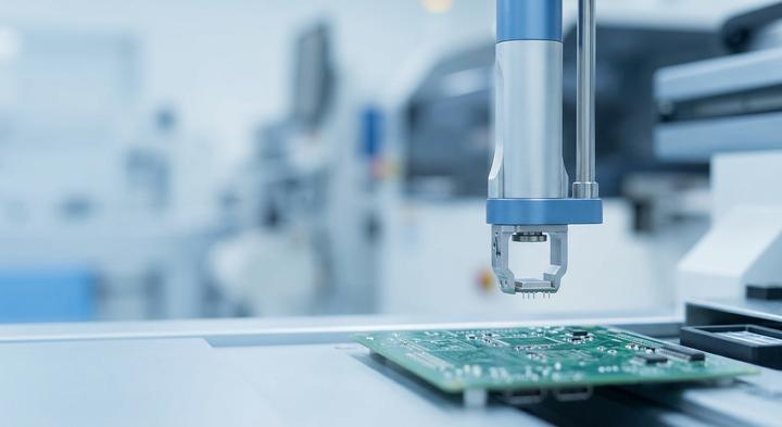
High-precision SMT lines require strict floor-level audits to guarantee component placement accuracy.
How do you audit an SMT line in Shenzhen to verify your electronic components are genuine and properly mounted?
Ignore the pristine showroom samples and the polished PowerPoint Slides. How you secure Demanding Floor-Level Proof is by walking straight to the active machinery with this Audit Matrix in hand.
Floor-Level SMT Audit Matrix
| Inspection Station | The Practical Question to Ask | What Evidence to Inspect on the Floor | Red Flag | YGhao’s Control Protocol |
|---|---|---|---|---|
| Incoming Material & Feeder Racks | How do you trace active component reel lot numbers from the feeder racks back to their origin certificates? | Pick an active feeder loaded with display driver ICs for your custom digital clock. Have the operator scan the reel barcode and pull up the original factory Certificate of Conformity (CoC) in the ERP within two minutes. | Hand-written labels, missing manufacturer barcodes, or reels that are not logged into the warehouse tracking system. | All incoming active ICs and oscillators are logged into a real-time MES with unique QR codes mapping each reel directly to its active feeder. |
| Reflow Calibration & AOI | How is the AOI calibrated specifically to prevent thermal stress damage on sensitive clock oscillators? | Look at the active AOI screen. Verify the system is running a specialized 3D-AOI profile that checks solder fillets on 32.768 kHz crystal terminals for height, volume, and micro-cracks. | SMT lines running generic passive AOI profiles that inspect sensitive timing components under the same loose tolerances as basic 0805 resistors. | Dedicated thermal reflow profiles limit peak temperatures near the oscillator block, backed by automated 3D-AOI sequences inspecting 100% of crystal terminals. |
| Functional Test & Burn-In | How do you eliminate early-life segment or display driver failures before packaging? | Check the functional testing fixtures. Ensure 100% of finished assemblies are loaded onto active test racks where every single LED segment is illuminated under high-stress thermal cycles. | Assemblies that bypass burn-in altogether, or visual testing setups that rely on human eyes to spot flickering display pixels. | Every module undergoes high-stress burn-in cycles with automatic current-draw monitoring to isolate weak LEDs or failing drivers before casing. |
This level of on-site scrutiny is what prevents a custom digital clock project from failing in the field six months after shipment. When display segments start flickering or the clock drift exceeds five minutes a month, the issue is almost never a bad schematic. It is usually a component reel swapped on the fly or an uncalibrated reflow profile that micro-fractured the crystal’s solder joint. If a supplier refuses to let your QC team verify these specific floor-level touchpoints, they are asking you to buy their marketing deck rather than their actual manufacturing capability.
Speeding Up Low-Volume NPI: Moving from CAD Files to Golden Sample with YGhao
Once those validation milestones and structural checks are locked, you face a different bottleneck: finding a factory that will actually run a low-volume custom digital clock project without pushing it to the back of the queue. Most high-volume SMT lines in Shenzhen are built for continuous runs; they make their money keeping machines moving, not resetting pick-and-place feeders for small batches. When your run is only 100 to 5,000 units, you get pushed aside the moment a million-unit consumer order comes in. YGhao operates specifically in this mid-volume space. Because we are an engineering-led team rather than a rigid contract assembler, we handle custom segment glass NRE development, noise-insulated PCB trace routing, and short-run assembly under one roof. If you split the work between a display broker, a freelance board designer, and an assembly house, you spend weeks acting as a middleman when components don’t line up. We keep the entire loop in-house to bypass those hand-off delays.
This integrated setup speeds up the critical pre-production engineering review where layout errors usually stall tooling. To initiate the review, submit your DXF casing boundaries, electrical schematics, and Bill of Materials (BOM). Our engineering team will run a 48-hour Design for Manufacturability (DFM) check, verifying component heights, pad geometry, and oscillator isolation clearances before we ever cut an SMT stencil. This screen-level verification catches mechanical and electrical conflicts early, ensuring your first physical run delivers a line-ready Golden Sample. Send your initial DXF files and schematics to our engineering team today to receive a complete DFM review and a production-ready cost estimate.