Developing a Custom Digital Clock with Temperature and Humidity Sensors: A Multi-Function Design Guide
Thermal Coupling: Why Standard Enclosure Designs Skew Digital Clock Sensor Readings
On a 6:00 AM test run of a newly assembled custom digital clock batch, the diagnostic display digits tell a quiet lie within fifteen minutes of power-up. The integrated ambient temperature reading creeps upward, eventually settling up to 5°C higher than the actual room environment. This is not a calibration defect, nor is it a faulty batch of silicon. It is a classic failure of Thermal Coupling. Inside a standard closed enclosure, a temperature sensor does not measure the ambient room; it measures the micro-climate of the chassis itself. Multiplexed LED driver chips and linear voltage regulators constantly shed excess power as heat, trapping thermal energy inside the sealed plastic housing. Punching generic slotted vent patterns into off-the-shelf plastic housings fails to solve this because the primary path of thermal energy is board-level conduction—heat travels directly through the PCB’s copper ground planes into the sensor’s solder pads.
For procurement teams sourcing these displays for hospital wards, cold-storage warehouses, or smart building management systems, this thermal drift makes remote telemetry useless. A display that falsely reports a 24°C room as 29°C triggers premature HVAC cycles, corrupts compliance logs, and wastes energy. Software offsets cannot fix this because the drift is dynamic, fluctuating constantly based on LED brightness levels, display duty cycles, or Wi-Fi transmission bursts. Furthermore, stagnant air pockets inside poorly ventilated custom cases trap micro-climate dampness, delaying the sensor’s response to actual environmental humidity changes by 15 minutes or more.
Solving this requires physical isolation before cutting expensive injection tooling molds. At YGhao, we handle this by designing routing cut-outs and independent internal sub-chambers that physically separate the sensor module from the main system heat sources. This upfront engineering prevents the six-week delays and costly rework of modifying finished steel molds. When evaluating suppliers for a custom digital clock with integrated telemetry, the rule of thumb is simple: if the initial PCB layout lacks a physical routed air gap separating the sensor’s copper plane from the driver board, the temperature reading will skew.
Component Selection: Balancing Sensor Precision, Display Thermal Output, and Tooling Cost
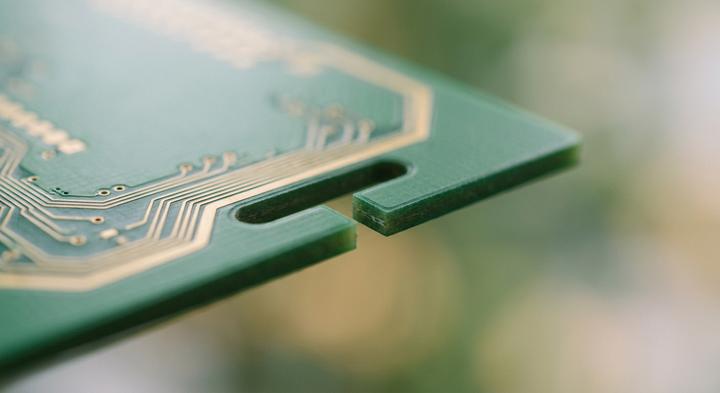
Routed thermal isolation slots in the PCB prevent lateral heat conduction to the sensor.
How do you choose between an analog thermistor and a digital sensor for a custom digital clock display without spiking manufacturing costs?
Sourcing custom industrial displays with integrated telemetry requires balancing high-precision demands against unit-cost constraints. For cleanroom or hospital installations, a ±0.2°C margin is non-negotiable, while warehouse floors run fine on ±1.0°C. Resolving this tension requires tracking how sensor selection impacts assembly-line throughput, where downstream calibration costs can easily double the true price of a cheap analog component.
An analog NTC thermistor is cheap upfront but requires dedicated ADC channels, pull-up resistors, and individual factory-level calibration to account for board-level trace impedance and variance. This manual line-calibration slows down production. Conversely, a digital CMOS IC sensor (such as the Sensirion SHT series) integrates the sensor, ADC, and calibration coefficients on-chip, communicating over I2C. This eliminates line calibration entirely and resists high-frequency signal noise on busy factory floors.
Display selection also shapes this thermal environment. Multiplexed LED grids draw significant current and generate localized heat, requiring strict current limits or routed PCB isolation air gaps to prevent telemetry skew. In contrast, low-draw segment LCDs run completely cool but need backlights in dark bays. For dust or washdown environments, replacing open venting slots with hydrophobic ePTFE breathing membranes keeps moisture out without trapping hot air.
| Customization Parameter | Standard Clock Baseline | Sensor-Integrated Configuration | Key Engineering Challenge | Unit Cost Impact |
|---|---|---|---|---|
| Sensor Type | Raw analog NTC thermistor (±1.0°C) | Digital CMOS IC (I2C, ±0.2°C) | Shielding high-frequency line noise and routing trace isolation | +$0.80 to +$1.50 |
| Display Tech | Multiplexed LED grid | Monochrome segment LCD panel | Backlight thermal profiling and driver board separation | -$0.50 to +$1.20 |
| Ingress Rating | Open slotted venting (IP20) | Hydrophobic ePTFE membrane (IP65) | Air exchange vs. high-pressure water sealing | +$0.40 to +$0.90 |
| PCB Assembly | Double-sided FR4 layout | Thermal-relief routed substrate | Eliminating lateral heat conduction via milled physical air barriers | Minimal BOM; +$150 tooling |
Strategic Trade-Offs for OEM Procurement
For production runs exceeding 5,000 units, selecting a pre-calibrated digital CMOS IC and an integrated ePTFE membrane reduces the total cost of ownership by eliminating quality control bottlenecks and field failures. At YGhao, we optimize sensor placement and display drive currents during the prototyping phase to protect your assembly yield.
When drafting your RFQ, remember that saving eighty cents on an analog thermistor usually costs five dollars in factory calibration labor and field warranty claims.
Application Blueprints: Customizing Display Panels and Housings for Demanding Environments
A QA engineer at 5:00 AM spots a frost line creeping across the acrylic face of a newly mounted unit, indicating that local condensation is already pooling near the internal PCB. In industrial environments, standard digital clocks degrade rapidly when exposed to humidity spikes, fine dust, and aggressive washdowns. Overcoming this requires aligning the housing plastics, driver ICs, and protective coatings during the early design phase, long before steel molds are cut. Standard off-the-shelf enclosures are rarely optimized for these microclimates.
Dry Food Logistics For Sub-Zero Environments
For a blast freezer operating at -25°C, standard liquid crystal displays freeze solid and standard quartz crystals drift several minutes per month, making Zero Cold Storage an operational nightmare. Standard heaters are a lazy fix; they draw excessive power and introduce additional thermal points that worsen condensation. A more reliable custom digital clock relies on low-temperature crystal oscillators and high-visibility segment LEDs designed to handle thermal transitions from a 25°C loading dock to sub-zero storage. Protection comes from a high-solids polyurethane conformal coating applied via selective spray, sealing the PCB against the moisture of rapid defrost cycles without trapping operating heat.
Traffic Public Terminal and Smart Offices In Dense Hubs
Managing hardware across Traffic Public Terminals and Smart Offices In major municipal networks means dealing with extreme light shifts and communication dropouts. High-lux overhead lighting washes out standard LEDs, requiring high-contrast reflective LCDs paired with flush-mount bezels that resist dust accumulation in structural seams. These systems daisy-chain over Modbus RTU or RS485 protocols to synchronize secondary displays to a master controller. To prove these units won’t lock up when the HVAC fails, YGhao runs physical prototypes through environmental testing chambers, performing 48-hour humidity sweeps and continuous thermal sweeps including a cold soak at -10°C and peak heat testing at 50°C before releasing the design to the SMT lines.
Sterile Clinical Cleanrooms and Laboratory Bays Sterile Configurations
Deploying equipment into Sterile Clinical Cleanrooms and Laboratory Bays Sterile zones introduces intense chemical exposure, as staff spray down every surface with aggressive sanitizers like isopropyl alcohol and hydrogen peroxide. Standard polycarbonate casings quickly micro-crack or yellow under these agents, so the enclosure must use chemically resistant polymethyl methacrylate (PMMA) or stainless steel flush-mount front panels. Since clinical facilities demand periodic sensor validation to maintain compliance, the clock housing integrates external calibration ports so field technicians can verify the internal digital sensors without compromising the room’s positive air pressure seal. When specifying cleanroom displays, verify the chemical compatibility of your lens polymer with the specific brand of sterilizing agent used on-site rather than relying on a generic IP65 rating.

Controlled sterile environments ensure multi-point sensor calibration remains accurate.
PCB Layout and Firmware Pitfalls: Engineering Mistakes That Distort Sensor Readings
Trace layout and firmware loop intervals dictate whether a custom digital clock delivers accurate ambient telemetry or simply measures its own internal operating heat, avoiding the engineering mistakes that distort sensor readings. Three physical design choices determine whether a display’s temperature probe actually works or just reports system heat.
“The sensor can share the main ground plane without affecting its thermal accuracy.”
A shared copper ground plane functions as an efficient thermal bridge, conducting heat from driver ICs and voltage regulators directly into the sensor’s silicon die. This thermal path easily skews ambient temperature readings upward by 3°C to 5°C. Fixing this requires routing physical relief slots—literal air gaps—into the FR4 substrate around the sensor. This isolation blocks lateral heat transfer, forcing the electrical signals to travel along narrow, serpentine traces that lack the thermal mass to conduct ambient errors.
“Querying the digital sensor continuously in the main firmware loop ensures the most responsive display.”
Continuous querying warms the chip. Every I2C or SPI transaction draws a brief current spike; when repeated in an uninterrupted loop, this active switching generates micro-calories of localized heat that cannot escape the tiny surface-mount package. The firmware must command the sensor to enter a low-power sleep mode, waking it to sample the environment only once every 30 to 60 seconds. A reliable ODM like YGhao verifies these sleep-state current draws during initial board bring-up rather than trusting default software libraries to manage power saving automatically.
“Placing the sensor directly behind an open enclosure vent is safe as long as the housing is plastic.”
Open-air vents allow the ambient atmosphere to circulate, but they also act as physical entry paths for electrostatic discharge (ESD) from a user’s fingertips. Without a transient voltage suppressor (TVS) diode positioned directly behind the vent on the PCB trace path, a static spark will jump the air gap, lock up the sensor, or corrupt the communication bus. Protective TVS diodes must be placed at the immediate entry boundary to ground these spikes before they propagate to the main microcontroller.
Before approving any custom layout, check the Gerber files for physical routed air gaps around the sensor—if the copper plane is continuous, the temperature reading will drift.
Factory-Floor Quality Checks: Auditing SMT Runs and Sensor Calibration Bays
While deciding between a digital sensor and a cheap thermistor protects your upfront BOM, those design choices only hold up if the assembly line doesn’t cook the sensor during reflow. Evaluating Floor Quality Checks requires looking past paper ISO certs to see how the SMT ovens run and how calibration data is serialized on the actual boards.
| Factory Floor Area | Audit Verification Checklist | Substandard Supplier Practice (Red Flag) | YGhao Calibration Standard |
|---|---|---|---|
| Reflow Line | Audit real reflow profiles; verify thermocouple loggers run directly on test-board pins to check sensor polymer exposure. | Using generic profile presets without board-level thermal profiling. This risks melting or baking the internal sensor membranes—a silent Red Flag that ruins accuracy before shipment. | Automated profiling via KIC systems. Peak reflow is capped at 245°C; dwell time above 217°C is limited to 60 seconds to protect membranes. |
| Sensor Calibration Bays | Verify if the factory uses sealed, reference-grade environmental chambers with controlled laminar airflow or just runs open-air checks. | Performing “ambient checks” directly on the open assembly floor. Unregulated shop drafts, local heat from SMT ovens, and humidity spikes make the baseline calibration worthless. | Inside our Sensor Calibration Bays Now, we run automated, multi-point calibration in sealed chambers using NIST-traceable master references with ±0.1°C certified tolerances. |
| Circuit Testing | Review test fixtures to ensure they isolate and test the sensor’s voltage rails, communication buses (I2C/SPI), and actual display current draw. | Basic “power-on” tests that only verify if the custom digital clock screen lights up, ignoring voltage noise or microamp-level current leakage. | Dedicated automated bed-of-nails fixtures measuring voltage rails (3.3V ±0.05V) and active/standby currents on every PCB. |
| Data Serialization | Trace how calibration offsets are logged. Ensure offset coefficients are linked to individual PCB serial numbers to manage long-term RMA claims. | Hardcoding static offsets into the main firmware batch or failing to maintain central records of individual component performance. | Storing unique calibration coefficients inside each board’s EEPROM, linked to our central database via a laser-etched QR code. |
Catching these drift issues on the line prevents bulk field failures that only show up after a custom digital clock runs for three weeks in a cold storage or cleanroom installation. If you are auditing prospective vendors, do not let them handwave these steps; ask to see their actual real-time oven logs and chamber sensor specs. We keep full database traces of these tests for every batch, and our engineering desk can walk your QA team through our live calibration fixtures during your next procurement review.
Tooling and DFM Hand-Off: Moving Your Sensor Clock Design to High-Volume Production
Now that the display panel decisions sit in a clear table, the real operational challenge is moving your sensor clock design into physical manufacturing. Transitioning your custom digital clock from a 3D CAD model to high-Volume Production While avoiding physical defects requires more than just exporting a file. A standard Design for Manufacturing (DFM) check focuses heavily on tooling physics: adjusting wall thicknesses to sit between 2.0mm and 2.5mm to avoid sink marks on the display bezel, and establishing a 1.5 to 2-degree draft angle for textured plastic finishes. Custom steel injection tooling typically demands a 25 to 35-day window for mold fabrication and T1 sample approvals, a timeline that many procurement managers overlook. For low-volume pilots under 500 units, you can completely bypass this heavy capital expense by CNC-machining off-the-shelf plastic or aluminum enclosures. But once you scale past 1,000 units, the upfront tooling amortization makes sense; setup friction like SMT stencil fees and custom testing-jig wiring are quickly absorbed by the plummeting per-unit part cost.
Before you lock in your casing dimensions, let our R&D desk review your physical files. Upload your 3D CAD files (STEP format) or system schematics to YGhao for a thorough structural and thermal DFM assessment. We will analyze your ventilation pathways, joint tolerances, and internal ribbing to ensure your integrated sensors are insulated from board heat, saving you from a costly post-mold redesign after the steel is already cut.