Launching a Custom Digital Clock Line: Managing Mold Tooling Budgets and Pre-Production Timelines
Why Your CNC Clock Prototype Looks Perfect While Mass Production Runs Risk Alignment Failures
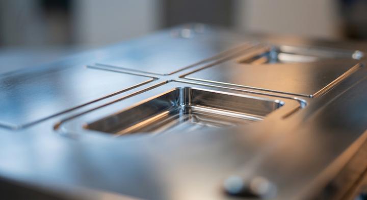
Precision tool steel molds ensure dimensional stability and seamless housing alignment during mass production.
A quality engineer under a 6:00 AM inspection lamp holds a hand-finished, CNC-machined custom digital clock prototype that looks flawless—only to find that the first injection-molded units off the production line arrive with a stubborn 0.2mm gap along the housing seam. This visual defect is rarely an assembly error. Prototyping methods like CNC-machining solid PMMA blocks or SLA 3D printing completely bypass the thermal stress, shrinkage, and cooling contraction that occur when production-grade ABS or polycarbonate is injected under high pressure into steel tool cavities. The prototype looks perfect because it bypassed the physical realities of high-volume manufacturing entirely.
On a manual bench, a skilled technician easily nudges a board into place to compensate for a 0.15mm shift in an internal PCB mounting boss. On an automated assembly line, that tiny shift triggers a chain reaction: crooked screen alignment, light bleeding between LED digits, and micro-cracks in solder joints. The initial prototype is a functional proof of concept, not a tooling blueprint. Moving to hard steel requires upfront Design for Manufacturability (DFM) audits—specifically mold flow simulation and sink-mark analysis—to protect your tooling budget before metal is cut.
When we run pre-production audits at YGhao, we start by mapping how the PCB tolerances interact with the enclosure tooling before the mold layout is locked. To catch these layout issues early, we put together a straightforward pre-production DFM checklist covering draft angles, wall thickness, and boss reinforcements. As a safe rule of thumb for clock enclosure tooling, lock down your PCB mounting tolerances to half the thickness of the outer housing bezel before signing off on the mold layout.
Tooling Cost Breakdown: Comparing Steel Grades, Mold Cavities, and SMT Stencil Timelines
How much does custom digital clock tooling actually cost to set up?
Non-recurring engineering (NRE) fees for a custom digital clock are split between physical plastic injection molds and surface mount technology (SMT) line setup. Choosing between budget-friendly P20 soft steel and polished S136 hardened steel dictates whether your enclosure stays dimensionally stable past 50,000 units or begins to show flash at the seams. This guide breaks down the actual cost factors, cavity economics, and electronics setup times across different production volumes.
| Buyer Profile | Tooling Decision Factors (Steel & Cavities) | Electronics & SMT Fit | Estimated Upfront NRE | Primary Risks & Verdict |
|---|---|---|---|---|
| Niche/IoT OEM (1,000–5,000 units) Startup or custom industrial clock run. | P20 Soft Steel (50,000-shot life limit). Single-cavity tool to minimize capital exposure. | Standard laser-cut stencil; 2–3 days basic programming for custom driver IC. | $3,500 – $6,000 | Verdict: Ideal for low-risk market validation. Risk: Tooling wears out rapidly if volume scales, necessitating a rebuild. |
| Mid-Market Brand (5,000–20,000 units) Standard commercial retail digital clocks. | P20 or S136 pre-hardened. 2-cavity mold to optimize cycle times. | Stencil with solder paste inspection (SPI); dedicated firmware loading and calibration. | $6,500 – $12,500 | Verdict: Best balance of upfront cash flow and unit cost. Risk: Core alignment shifts over time if P20 is pushed past its limit. |
| Industrial & Enterprise (50,000+ units) High-volume custom digital clock deployments. | Polished S136 Hardened Steel (500,000+ shots). Multi-cavity (4+) high-precision tool. | Double-sided SMT line; 100% automated optical inspection (AOI) + SPI; high-speed programming. | $16,000 – $30,000+ | Verdict: Lowest long-term unit cost; highly amortized NRE. Risk: High initial capital commitment; long lead times for mold modification. |
Three Production Scales: Matching Your Target Volume to the Right Tooling and Component Path
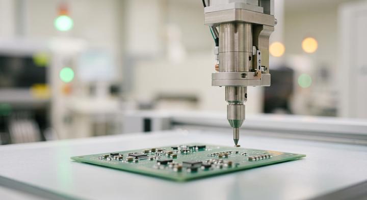
High-speed SMT assembly lines place driver ICs and passive components with sub-millimeter accuracy.
A procurement manager staring at a 7:00 AM spreadsheet realizes their custom digital clock launch date is locked, but the display vendor just dropped a bomb: custom LED/LCD glass fabrication and backlight molds realistically add 20 to 30 days to standard assembly timelines. This delay isn’t a factory error; it’s a physical tooling constraint. If you don’t match your production scale to the right tooling path from day one, you end up paying high-volume tooling prices for low-volume runs, or worse, waiting on slow prototype processes for a mass-market launch.
The Low Volume Specialty Order
When an industrial customer needs exactly 2,000 Units for a specialized control panel, buying a custom injection mold is almost always a mistake. We recently worked on a project where the buyer budgeted $12,000 for a custom mold, only to face a late-stage PCB revision that shifted an interface port by three millimeters. Instead of waiting six weeks and spending a fortune to recut steel, the practical alternative was modifying standard, off-the-shelf plastic enclosures using five-axis CNC milling and applying a custom screen-printed acrylic bezel to mask the modifications. For any run under 2,500 units, post-machining catalog enclosures bypasses custom tooling fees entirely, preserving both your budget and your timeline.
The Mid Scale Bedside Clock
Once your forecast reaches 10,000 Units, catalog plastics are no longer cost-effective, yet your design still needs to retain enough flexibility to survive mid-run firmware optimizations. For a mid-market consumer product like an IoT Bedside Clock, the optimal path is a two-cavity P20 steel mold paired with standard, non-automated SMT lines. P20 semi-hardened steel handles this volume without wear but remains soft enough to modify via EDM if a button boss needs a late-stage tweak. Standard SMT lines also allow you to flash and test the microcontrollers in smaller batches, giving your software team room to patch ambient light sensor calibration issues or wireless protocol bugs before they are sealed into final assembly.
The High Volume Display Project
At 50,000 units, the manufacturing strategy shifts from protecting design flexibility to squeezing out every millisecond of cycle time. A high Volume Display Project at this scale requires S136 hardened steel multi-cavity molds and fully automated SMT lines equipped with inline solder paste inspection (SPI). Hardened S136 steel is a major upfront capital expense, but it drops your injection molding cycle times by up to 60% and holds sub-millimeter tolerances over millions of shots. The catch is total rigidity: once the automated SPI and pick-and-place lines are running, physical changes mean scrapping a highly polished tool, making deep pre-production DFM checkouts your only real insurance.
Never sign off on multi-cavity hardened steel tooling until your firmware has survived a thousand hours of continuous soak testing without a single crash.
Four Costly CAD and SMT Mistakes That Blow Out Production Budgets
Designing a custom digital clock is where most margins get eaten before any plastic is shot. Leaving structural and thermal mismatches between CAD files and SMT lines is how you end up with Production Budgets Unchecked. It takes very little oversight to trigger over $10,000 in tooling modifications or scrap an SMT batch because a physical part didn’t behave like its 3D design.
“We can save display bezel width by keeping the vertical housing walls at a strict 90 degrees.”
A vertical wall without draft ruins the finish. Plastic shrinks around the steel core during cooling. Trying to eject a 90-degree wall without a 0.5 to 1.5-degree draft means the custom digital clock housing drags, leaving scuff marks along the bezel. To achieve a thin bezel with zero visible draft, the toolmaker must mask the draft internally or offset the shut-off—you cannot force a straight-walled part out of a standard tool.
“A 0.1-millimeter clearance is a safe default for fitting the acrylic display lens into the molded ABS casing.”
This assumes plastic and acrylic shrink at the same rate. ABS shrinks up to 0.7%, while the acrylic lens barely moves. Ignoring these divergent rates in CAD results in loose, rattling lenses or pinched buttons that stick. Make your engineering team calculate the worst-case tolerance stack-up under maximum material conditions to ensure the lens snaps in securely without putting stress on the display panel.
“If the PCB layout passes design-rule checks, the SMT line can run our dense LED driver ICs without custom profiling.”
A standard DRC only checks trace clearances, not thermal physics. Clock designs often feature dense pin placements on custom LED driver ICs near heavy copper planes, which act as heat sinks and cause bridging. Achieving a high first-pass yield requires your manufacturing partner, such as YGhao, to run solder paste inspection (SPI) and adapt stencil thickness locally rather than running a generic reflow profile.
“Tooling wear is only an issue for high-volume runs, so we don’t need tool lifespan guarantees in our contract.”
Assuming a tool rated for 50,000 shots delivers identical quality on shot 49,000 is an expensive mistake. Cheaper pre-hardened steel molds show wear at shut-off surfaces early, causing flash defects that require hand-trimming after 30,000 cycles. Secure a guaranteed tool lifespan in your contract that commits the factory to maintain, repair, or re-machine the mold cavity at their own expense if dimensional drift occurs.
As a rule of thumb for any custom enclosure: if the factory cannot show you their tolerance stack-up calculations on the housing-to-lens fit, don’t let them cut steel.
Vetting a Sourcing Partner: Physical Evidence to Request Before Tooling Kickoff
Deciding on production volume limits is only the first step; the real operational risk begins when you trust a factory floor to execute your sub-millimeter custom digital clock specifications. When vetting an overseas Sourcing Partner, trusting verbal quality assurances is a reliable path to delayed shipments and housing seams that do not align. Forcing a supplier to provide verifiable Physical Evidence—before steel is cut or components are ordered—is the only practical way to confirm they possess the engineering rigor required for high-yield runs.
Verification Protocols Before Cutting
| Vetting Checkpoint | Expected Hard Evidence | Critical Red Flag | Responsible Party |
|---|---|---|---|
| Toolroom Caliber & Mold Steel Integrity | Raw steel mill certificates with heat numbers; EDM wire-cut calibration logs showing tolerances within ±0.01 mm. | Generic “tool steel” claims without traceable batch certificates; inability to provide machine calibration logs. | Supplier provides metallurgical test data; Buyer verification team reviews heat numbers. |
| SMT Lines & Electronics (Display Drivers) | Real-time Automated Solder Paste Inspection (SPI) reports; post-reflow Automated Optical Inspection (AOI) logs for components like LED Display Drivers. | Manual visual inspection as the sole QC step; refusal to share active defect tracking logs. | Supplier export-quality team provides SMT run logs; Buyer engineering lead signs off on yields. |
| Environmental Testing & ESD Safety | In-house facility logs showing 1.2m drop tests; calibrated thermal chamber test data; daily ESD wrist-strap monitor logs. | Subcontracted testing claims without lab certificates; missing ESD grounding cables at manual assembly line stations. | Supplier production manager provides signed calibration sheets; Buyer verifies operating procedures. |
| Tooling Design Sign & Optimization | A Comprehensive Design for Manufacturability (DFM) report featuring mold-flow simulations, wall-thickness analysis, and strict PCB clearance audits. | Oral agreements to “fix tolerances during trials” without updating the master CAD drawing. | Supplier’s mechanical engineering team generates the DFM report; Buyer’s technical lead approves. |
As a baseline Request Before Tooling Kickoff, a buyer should insist on these specific documents rather than accepting generalized quality promises. This step is not about unnecessary paperwork; it is about verifying that the factory’s actual manufacturing capabilities match the marketing claims on their website. At YGhao, we make this transparency standard procedure, delivering full steel certifications, automated SMT yield logs, and detailed DFM reports before any tool-steel cutting begins. Before you commit capital to an injection mold, require your manufacturer to put this raw proof on the table.
From Steel to Assembly: A Structured Path for Your Custom Digital Clock Run
While balancing your tooling class against production volume limits upfront capital risk, the real test of any custom digital clock design is the physical assembly line. This critical phase centers on a 15-day tuning window between the initial T1 sample and final T3 approval. During this window, engineers must resolve cosmetic issues like sink marks and heavy parting lines, but the trickiest fixes are mechanical. For a custom digital clock, this means micro-tuning the internal casing snap fits to prevent creaking, adjusting button actuator travel to hit a precise click force, and placing physical light baffles to stop bright LED backlights from bleeding into adjacent display segments. The electronics demand equal care. Before sealing the display and board assembly inside an ABS or polycarbonate enclosure, every display module undergoes Functional Circuit Testing on custom-designed jigs that subject the components to thermal stress and physical vibration to catch weak solder joints early.
Handling this work at scale requires serious factory-floor execution. We back our process with concrete capabilities: injection molding presses up to 400 tons that reliably hold critical plastic dimensions within 0.1 mm, alongside SMT lines mounting small passive components at 40,000 chips per hour. We typically schedule a pilot run while the tooling is being polished so that your engineering team can sign off on physical golden samples before mass assembly begins. To get an accurate manufacturing blueprint, we recommend a complete Design for Manufacturability review before any metal is cut. If you sign a bilateral NDA and share your 2D/3D CAD files or Gerber PCB layouts, our engineering team will provide a comprehensive DFM assessment and a transparent tooling cost projection, identifying potential clearance or draft issues before they turn into costly mold modifications.