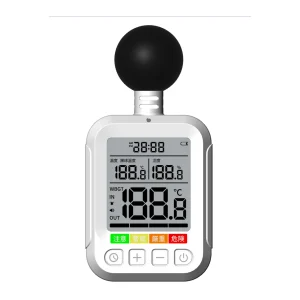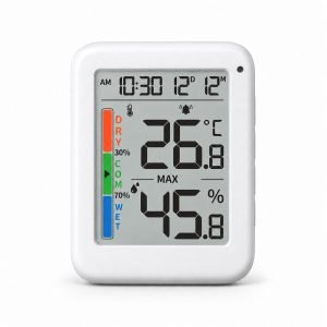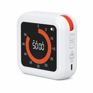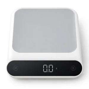
Leveraging YGhao’s Design Capabilities for Your ODM Custom Digital Hygrometer Program
Why Shell Design Rules Field Reliability: The Real-World Cost of Condensation in Custom Digital Hygrometers

Advanced polymer housings prevent moisture migration to the internal circuit board.
With Custom Digital Hygrometers Pulling a unit out of a 20°C cold-storage zone directly onto a 25°C loading dock, the housing design faces a real-world test in seconds. In high-humidity transit or food logistics, desktop prototypes always look flawless. They pass dry bench tests without a hiccup, only to fail within thirty days of field deployment. The issue is rarely a bad sensor element. Instead, it is almost always a styling compromise in the plastic casing. When shell airflow paths are designed for cosmetic appeal rather than thermal transition, temperature changes turn ambient moisture into a physical trap, pooling water directly onto the circuitry and causing permanent sensor drift.
This month-one failure rate highlights the quiet friction between premium product styling and actual field survivability. Procurement teams often get caught up in how a casing looks on a conference table, but at YGhao we look at the tooling tolerances first. High-end industrial design is useless if the injection-molded halves warp by even 0.1 mm under thermal stress. That tiny gap is more than enough to let humid air seep in. To survive in commercial environments, you have to separate the exterior aesthetics from the actual sensor environment. This requires isolating the sensor cavity from the main PCB housing with tight silicone overmolding and hydrophobic vents.
If you are sourcing these devices, do not base your ODM selection on polished 3D renders. You need to inspect the internal layout, specifically where the sensor chamber meets the rest of the PCB enclosure. Many low-cost designs run the sensor trace directly into the main battery compartment without a physical gasket. A simple rule of thumb for your next engineering call: if the sensor compartment shares an unsealed physical void with the battery or main processor, moisture will migrate and bridge the contacts. It does not matter how sleek the outer shell feels if a single hot-to-cold cycle shorts the main board.
Comparing Enclosure Architectures: Resin Selection and Sensor Chamber Isolation
Which plastic resin actually survives five years of daily chemical sanitization in a clinical lab without micro-cracking?
Selecting the raw polymer for a custom digital hygrometer is a direct trade-off between physical impact resistance, chemical exposure, and sensor responsiveness. Standard ABS is cost-effective for indoor office HVAC systems but degrades rapidly under UV exposure or clinical sanitization. To protect sensitive electronics, modern designs isolate the measurement path using molded internal baffles, swapping hand-placed silicone gaskets for co-molded thermoplastic elastomers (TPE) to eliminate manual assembly defects.
| Enclosure Material | Target Application (Buyer Type) | Response Rate vs Ingress Rating | Structural Verdict |
|---|---|---|---|
| High-Impact ABS | Budget indoor HVAC monitoring (Commercial Installers) | Rapid response via passive slotted vents; limited to IP40 | Yellows under UV; micro-cracks under alcohol. Avoid for medical/clinical use. |
| PC/ABS Blend | Industrial logistics & cold-chain warehouse tracking (Sourcing Managers) | Moderate response; hits IP54 with localized elastomeric gaskets | Balanced choice; weld-line vulnerability near complex vent geometries. |
| Pure Polycarbonate | Clinical labs & pharmaceutical washdown zones (OEM/ODM Buyers) | Slower response; requires membrane-protected IP67 vents | High shrink rate during molding. Medical-grade PC is specified for ultrasonic welding. |
Isolating the Measurement Pathway
The physical interface between the housing resin and the sealing gasket determines long-term field stability. While hand-placed silicone gaskets are cheap, they rely on assembly workers positioning them perfectly every single time. A slight twist during a fast shift creates a micro-pathway for moisture. Co-molded thermoplastic elastomers (TPE) fuse directly to the polycarbonate frame during molding, which isolates the sensor chamber completely. This internal baffle prevents heat from the internal electronics from throwing off your ambient humidity readings. If your supplier cannot show you a mold-flow analysis proving they balanced the injection gates away from those thin sensor vent walls, the tool will produce stress concentration lines that crack under clinical cleanings. Never let the sensor cavity share raw air space with the battery compartment; that is where condensation gathers first.
Environmental Hardening: Tailoring the Custom Digital Hygrometer Bill of Materials
A QA lead on the 6:00 AM shift pulls a rack of test boards from a 20°C chamber, watches the display windows cloud with internal moisture inside ninety seconds, and immediately marks the entire sample batch as a failure. In rugged applications, moving from an idealized prototype to a hardened field unit requires matching the Custom Digital Hygrometer Bill of Materials to the precise environmental stressors of the environment. The component list cannot be a lazy copy-paste from a development kit; it has to evolve based on whether the device measures air in a shipping container, an office wall, or a sterile laboratory cleanroom.
Custom Spec: Cold Chain Logistics and Distribution
When cargo trailers move from baking loading docks into deep-freeze storage, the sudden pressure drop sucks warm, humid air straight through standard enclosure seals. For procurement managers trying to protect the PCBA without destroying response times, standard potting is a trap; it slows thermal equilibrium until the sensor lag exceeds twelve minutes. The real-world fix is an isolated internal sensor chamber sealed off from the main battery cavity, utilizing a hydrophobic PTFE membrane with a 0.2-micron pore size. This membrane blocks liquid water, preventing Condensation Transit In the electronics housing while allowing water vapor to reach the transducer in under four seconds. For these high-vibration routes, a physical gasket barrier between the sensor cavity and the battery compartment is the only way to keep moisture from migrating down the wire traces over ninety days.
High Volume: Building Automation Systems For Commercial Facilities
For facility engineers installing smart-office sensors, the real threat isn’t liquid water, but the localized heat pockets that build up inside the housing from a backlit LCD or a Zigbee transmitter. When the enclosure lacks vertical convection chimneys to channel this internal warmth away, the system consistently reports relative humidity values that are 2% to 4% lower than the actual room environment. At YGhao, we design these low-profile wall plates to run passive-convection channels that isolate active RF components at the top of the PCBA while keeping the physical sensor at the lowest intake grill. When sourcing at high volume, the safety check is simple: ensure the vendor’s mechanical CAD places heat-generating ICs in the upper hemisphere of the enclosure, completely decoupled from the sensor path.
Avoidable Sourcing Pitfalls: Three Mechanical Mistakes in Custom Hygrometer Tooling
A prototype that performs beautifully on a dry laboratory bench can easily turn into a high-scrap nightmare once you cut steel. Transitioning a custom digital hygrometer from a 3D-printed mock-up to high-volume injection molds introduces physical forces and chemical behaviors that desktop prints cannot replicate. If these mechanical blind spots are ignored during initial CAD sign-off, the result is field failures and cosmetic defects that no downstream QA line can inspect out of the product.
If the enclosure plastic looks clean, the internal sensor is safe from chemical fouling.
A clean-looking shell often masks an invisible threat: internal volatile organic compound (VOC) outgassing that permanently shifts capacitive sensor chips. When cheap polymers or uncured glues are sealed inside a warm enclosure, they slowly release vapors that coat the sensor’s thin-film dielectric, causing a progressive calibration drift weeks after shipping. The practical solution is to swap liquid adhesives for mechanical snaps and specify low-outgassing resins like medical-grade PC/ABS. If sealants are unavoidable, build a dedicated thermal baking step into the assembly line to fully cure the volatiles before final housing closure.
Uniform wall thickness is merely an aesthetic preference for the outer housing.
Non-uniform walls ruin both the cosmetics and the hermetic seal of your device. Thick zones cool slower than thin ones, creating uneven shrinkage that pulls the outer surface inward to form sink marks near display windows. More critically, this uneven shrinkage twists the main gasket groove, creating micro-gaps where ambient moisture bypasses the seal. Keep wall thickness variations under fifteen percent, using core-outs and structural ribs on the internal B-side to keep the housing stiff without adding bulk.
Tightening tolerances across the entire enclosure drawing ensures a premium-feeling device.
Over-specifying tolerances across the entire shell does not make the device feel premium—it just doubles tooling costs and drives up injection scrap rates. A seasoned toolmaker knows that holding a tight clearance on non-mating cosmetic edges does nothing but wear out the mold core faster. Focus tight tolerances strictly on critical interfaces, like the sensor chamber seal and PCB locating pins, while leaving general housing clearances more forgiving. We track these design rules under our internal Custom Hygrometer Tooling Three audit checklist to ensure we do not over-engineer non-critical dimensions at the expense of tool life.
Auditing the ODM Factory: How to Verify an Industrial Design Team’s Tooling Expertise
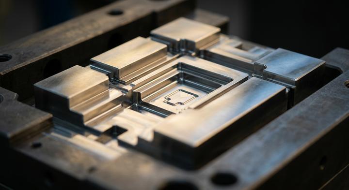
Rigorous DFM checks verify mold cavity draft angles and wall thicknesses before cutting tool steel.
While tailoring the bill of materials isolates the sensor from ambient battery heat, these layout choices only matter if the factory can translate the CAD files into steel. Evaluating an Industrial Design Team’s Tooling Expertise Once the 3D model is locked avoids the typical disconnect where an offshore subcontractor fails to execute the design.
Engineering Verification Checklist for Tooling Audits
| Audit Dimension | Required Verification Document | Factory Sourcing Blindspot | Quality Standard |
|---|---|---|---|
| Direct DFM Communication | Active CAD-to-CAM logs showing real-time feedback loop between designers and mold technicians. | Trading firms outsource files to freelancers, leaving subcontracted tooling shops to find drafting errors during steel cutting. | Co-located design and tooling teams under one roof, running real-time design checks during the layout phase. |
| Flow Simulation | Pre-tooling simulation reports detailing gate locations, fill times, shear stress, and air trap risks. | Subcontractors skip simulation runs to bypass license fees, leading to visible weld lines on the custom digital hygrometer’s outer bezel. | 100% mandatory simulation mapping on every tool design to optimize gate placement and prevent cosmetic weaknesses. |
| Color Continuity | Calibration logs from industrial spectrophotometers and raw Delta E (\Delta E) tolerance datasets across production lots. | Factory floor QC relies on manual human visual checks under office fluorescent lighting, leading to noticeable color drift between batches. | Spectrophotometer verification on every resin batch to guarantee strict Pantone matching to a tolerance of \Delta E < 1.0. |
Once a tool steel block is cut, correcting a misplaced gate or an un-vented cavity is not a simple software patch; it requires EDM rework, resets the lead-time clock by weeks, and degrades the tool’s lifespan. Sourcing teams cannot afford to treat these verification documents as optional paperwork. A factory that provides these live logs proves they own their manufacturing pipeline, transforming the industrial design from a conceptual mockup into an airtight, field-ready custom digital hygrometer.
Reducing Tooling Risk: How YGhao’s Integrated DFM Workflow Prepares Your Custom Shell for Production
Now that the bill of materials is hardened against field moisture and temperature cycling, the biggest hurdle left is transitioning from a 3D CAD model to a steel injection mold that actually runs at high yields. When styling, mechanical engineering, and mold-making are siloed across three different vendors, the buyer is the one paying for the inevitable translation errors. A housing with sharp corners and zero-draft vents looks crisp on a display screen, but it requires expensive lifters and slide mechanisms that blow past your tooling budget, or worse, causes uneven resin shrinkage that warps the critical sensor chamber sealing surfaces. By centralizing the industrial design and tool build under one roof, this integrated DFM Workflow Prepares Your Custom enclosure to run cleanly from day one. We identify wall-thickness variances, cosmetic gate locations, and draft issues while the design is still digital and cheap to modify, rather than finding a sink mark on a textured bezel after the tooling steel has been cut.
Avoiding these costly modifications is about getting a tooling engineer to look at your layout before you sign off on the steel. If you are aiming for high-yield Production Now, send your 3D CAD files, component envelopes, or hand sketches to the YGhao engineering team. We will review your draft angles, recommend gate placements to hide weld lines on cosmetic surfaces, and check your wall-thickness ratios to keep the sensor chamber flat. You will get a practical, redlined DFM feedback report that tells you exactly where the tool is likely to hang up and how to fix it before starting the mold build.