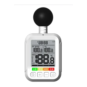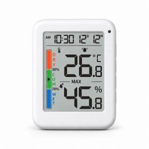
How to Launch a Low-MOQ Custom Digital Hygrometer Project Without Heavy Tooling Costs
The Post-Reflow Blind Spot: Why Your First Custom Digital Hygrometer Pilot Drifts

Abstract depiction of optimal airflow dynamics across structural components, critical for preventing dead-air pockets.
An SMT operator at 07:00 pulling the first ten boards of a new custom digital hygrometer run off the conveyor watches the digital tester display a relative humidity that drifts 12% below the ambient room baseline. The immediate reaction is to halt the line, suspecting a defective batch of ICs or a bridge under the sensor’s LGA package. In almost every case, the hardware hasn’t failed; it has simply hit the physics of lead-free SMT reflow. When polymer-based capacitive humidity sensors pass through a reflow oven peaking at 260°C, the extreme thermal profile bakes out every molecule of water trapped in the active sensing element. This extreme desorbtion leaves the sensor temporarily blind, reading artificially dry until it can slowly rehydrate. For procurement and engineering teams running a tight pilot schedule, this post-reflow recovery window is an invisible trap. Running a calibration cycle or a final QC check during this “dry-blind” phase bakes the error permanently into the EEPROM, ruining the accuracy profile and triggering an expensive, unnecessary batch rejection.
The hardware design itself often worsens this initial drift. Even a highly rated, calibrated digital sensor behaves like a cheap generic if the enclosure traps it in a dead-air pocket directly behind an LCD panel or a heat-generating battery. Achieving continuous, real-time air exchange is easy if you can afford custom injection molds, but that tooling destroys a small-batch pilot budget. A practical approach is modifying standard, off-the-shelf plastic enclosures using custom CNC milled slots. This keeps the initial project costs within reach while allowing the air to flow naturally over the PCB. At YGhao, we split the setup costs of PCB stencils and CNC milling modifications within our short-run NRE calculation. This ensures the pilot run balances mechanical protection with calibration reliability, preventing the dead-air trap without requiring a five-figure molding investment.
Balancing the Bill of Materials: Component Specifications vs. Tooling Costs
How do you reduce custom digital hygrometer tooling costs without sacrificing sensor calibration accuracy?
The short answer is you do not cut corners on the sensor element itself; you squeeze the physical board shape and the plastic housing instead. A high-precision relative humidity reading means nothing if your custom enclosure traps stagnant air or your complex PCB routing drains your pilot budget before you ship a single prototype. At YGhao, we split the setup costs of PCB stencils and CNC milling modifications to make sure your short-run economics actually make sense.
| Buyer Segment | Design Choice | Component Specifications | Cost Impact | Sensor Calibration Risk | Procurement Rule |
|---|---|---|---|---|---|
| Industrial OEM (High Accuracy) | MEMS capacitive sensor (I2C) vs. NTC resistor with custom-curved PCB layout | Standard scored rectangular boards instead of custom rounded outlines | Bypasses custom routing jigs and SMT stencil modifications, saving $1,200 | Thermal stress and sensor shift during reflow soldering if thermal isolation slots are omitted; ±2% RH accuracy requires isolation | Prioritize sensor placement over aesthetic enclosure curves; keep PCB shapes rectangular to avoid custom routing fees |
| Commercial Appliance (Mass-Market) | NTC thermistor + resistive wet-dry sensor for basic threshold detection | Generic multi-project wafer lines and generic laser-cut stencils | Setup fees remain under $150 with no custom tooling required | Severe calibration drift under condensing cycles (>90% RH) due to resistive element degradation | Only use resistive elements for basic wet/dry flags where precision and drift over time are secondary |
| Niche Industrial (Rugged Hardware) | Custom-molded protective plastic housing with integrated air channels | Standard stock enclosures with customized top-plate CNC cuts | Bypasses the initial $10,000 injection molding fee with low-cost CNC routing | Dead-air pockets inside standard housings slow sensor response times from 4 seconds to over 40 seconds | Never pay for custom injection molds for runs under 5,000 units when CNC-milled stock casings deliver identical airflow |
Balancing BOM vs. Tooling Realities
When analyzing Tooling Costs How you allocate your initial budget directly dictates your prototype’s commercial success. Squeezing every dollar out of the bill of materials too early usually leads to high NRE penalties elsewhere; a rounded PCB outline seems minor but introduces custom router bits and test fixtures that add over $1,500 in setup fees. Keep your PCB rectangular and your enclosure stock until your production forecast crosses the 5,000 units threshold where tooling amortization finally becomes profitable.
Three Roles, Three Truths: Who Verifies What in the First 30 Days
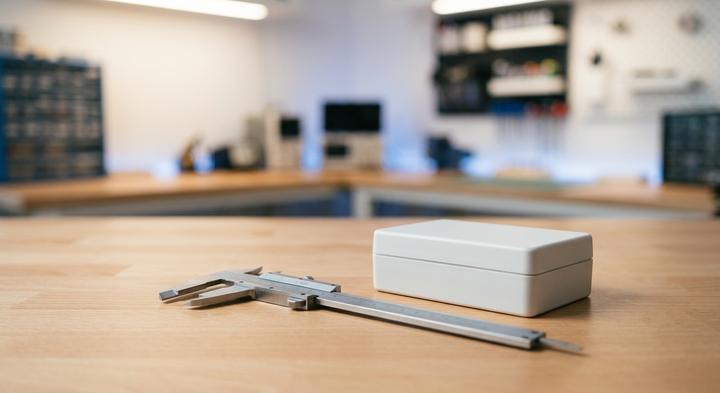
Precision physical validation of custom enclosure components during the initial prototype phase.
A test engineer squinting at a thermal camera feed at 10:00 PM spots a heat plume creeping across the FR4 board, slowly engulfing the relative humidity sensor. During the first 30 Days, bringing a custom digital hygrometer from a schematic to a physical, working pilot requires aligning three distinct perspectives: sourcing, hardware engineering, and product management. If these stakeholders operate in silos, you end up with a device that is either too expensive to build or too inaccurate to deploy. Successful development relies on addressing the real-world friction of physical design decisions early, ensuring that mechanical protection never compromises sensor calibration.
Scenario A: Sourcing a 500 Unit Pilot Without Tooling Traps
Sourcing leads looking at initial sample quotes often get caught by the low-MOQ bait where prototype units look cheap, but the subsequent production run price spikes because the vendor hid the cost of rapid injection tooling. This budget trap happens when a factory uses manual prototyping for the first twenty units but must build expensive steel molds to handle the next five hundred. To keep your initial run viable, we bypass custom molds entirely for low-volume phases by machining our stock plastic enclosures on internal CNC mills and splitting the setup fees for stencils within our engineering quote. This hybrid approach keeps unit costs stable and predictable, allowing you to test the market with a 500 Unit Pilot Without committing to high-cost tooling.
Scenario B: Hardware Engineering and the Climate Clearance Rule
A developer running a board-level thermal simulation is constantly fighting heat conducted through copper ground planes. If a digital relative humidity sensor sits too close to a linear voltage regulator or a micro-controller, the local temperature spikes, artificially lowering the humidity reading. Under our Climate Clearance Rule, we enforce a minimum 2mm clearance slot or a physical U-shaped router cutout around the digital sensor to decouple it from ambient PCB heat. Rather than discovering this calibration drift after assembling the boards, our Hardware Engineering team reviews raw Gerber files before making stencils to catch missing thermal bridges before they reach the SMT line.
Scenario C: Ergonomic Validation for Rugged Field Equipment
When Rugged Field Equipment goes out for validation, the data sheet’s paper specs mean nothing if a field technician wearing thick gloves cannot operate the interface. In these early Days An engineering team has to verify that the segment LCD remains clearly readable at a 45-degree angle under direct afternoon sun and that the custom silicone keypad has a distinct, physical snap. We run physical Ergonomic Validation tests using several elastomer durometers and custom casing textures so that the physical product feels like a professional tool rather than a cheap consumer toy. If your field testers cannot confirm an LCD reading at 45 degrees within five seconds, the internal PCB accuracy is completely irrelevant.
Where Hardware Pilots Fail: Three Costly Myths of Custom Digital Hygrometer Tooling
Your sensor’s datasheet means nothing if your casing traps dead air or leaks moisture. Enclosure geometry and thermal isolation dictate real-world accuracy far more than the nominal specs of the sensor itself.
A CNC-milled prototype casing is a perfect physical representation of our final molded production housing.
Milled prototypes are fine for checking mechanical fit, but they hide microscopic sealing tolerances that ruin early IP65 or IP67 testing. Tool marks from CNC bits leave tiny ridges along gasket paths. These ridges create micro-channels, letting ambient drafts bypass the main filter membrane and enter the sensor chamber. It looks like sensor drift on your bench, but it is just a leaky enclosure. Always verify seal integrity under positive pressure or via localized dye testing before cutting injection-mold tooling, or the actual plastic parts will fail to replicate your pilot’s bench performance.
The semiconductor factory already calibrated the sensor IC, so our board layout won’t affect its accuracy baseline.
Pre-calibrated silicon is only accurate in a thermally dead environment. Put a low-dropout (LDO) linear regulator or a high-current MCU trace near the sensor’s thermal pads, and your PCB copper becomes a radiator. This parasitic heat dries out the air pocket around the chip, dropping relative humidity readings by 5% to 15%. At YGhao, we solve this by routing physical thermal isolation slots around the sensor footprint. This decouples the IC from the board’s thermal dissipation while maintaining mechanical support, ensuring the sensor reads the actual ambient environment.
Skipping environmental chamber testing on a 500-unit pilot run is a safe way to preserve our launch budget.
Bypassing the chamber on a small run is a massive financial risk disguised as a saving. During SMT reflow, the oven’s heat drives moisture completely out of the sensor’s polymer membrane, shifting its calibration. Without a 24-hour hydration recovery phase followed by a chamber-verified two-point test at 10% and 80% RH, you cannot know if your units are reading true humidity or a warped post-assembly baseline. Saving a few hundred dollars on pilot-level chamber testing simply shifts those quality control costs onto your warranty support line.
Treat your 500-unit pilot with the exact same calibration and thermal hygiene as a million-unit program, or your customers will find the testing gaps for you.
Vetting Your Custom Digital Hygrometer Factory: The Verification Checklist
Now that the verification responsibilities for the first 30 days are assigned across your engineering and quality teams, you have to transition those internal commitments to the factory floor. Vetting Your Custom Digital Hygrometer Factory is not a paper-pushing exercise. This is why we rely on The Verification Checklist Once the roles are locked in, ensuring we test the vendor’s actual physical capabilities.
Most export sales agents will happily sign a contract guaranteeing ±2% relative humidity accuracy. What they do not tell you is that the polymer inside these sensor elements is highly vulnerable. Run those boards through a standard reflow oven without proper protection, or let volatile organic compounds outgas from nearby enclosure adhesives, and that accuracy spec drifts immediately. If a supplier cannot demonstrate exactly how they manage post-reflow moisture recovery and multi-point calibration, you are buying an unverified assembly of plastic and silicon, not an industrial instrument.
Negotiable Technical Audits
| Vetting Question | Required Proof | Watch Out For | Action Owner |
|---|---|---|---|
| Are calibration chambers validated with physical references? | Active, third-party certificates (NIST or ISO/IEC 17025) for reference hygrometers inside the active chamber. | Chamber software using fixed, hard-coded internal offsets or comparing against an unverified “golden sample” PCB. | Quality Assurance Lead |
| How are the dense 2x2mm sensor packages inspected post-reflow? | 3D Automated Optical Inspection (AOI) reports showing solder fillet height and volume profiling on the sensor pins. | Manual visual inspection with standard magnifying lamps. Solder bridging and micro-voids under low-profile packages are easy to miss. | Line Supervisor |
| Does each board have a serialized calibration history? | A live database sample where a PCB’s unique laser-etched QR code pulls up its exact multi-point calibration curve and raw sensor batch lot. | Batch-level logs or static CSV files where individual board drift cannot be isolated. | Systems Integration Engineer |
| What post-reflow sensor recovery protocol is executed? | Documentation of a dedicated environmental conditioning phase (exposing PCBs to 75% RH at 25°C for 24 hours) before calibration. | Calibrating PCBs immediately out of the reflow oven, which guarantees permanent, positive drift in the field. | Manufacturing Process Engineer |
Skipping these floor audits to save a few days on the pilot timeline always costs more in the long run. When first-batch failures hit the field, retrofitting thousands of sealed plastic housings is a fast way to burn through your engineering margin.
Mitigating Risk on Your Next Custom Digital Hygrometer Run
Now that calibration and SMT quality responsibilities sit with their respective owners, the actual challenge is finding a manufacturing partner that can execute these tight standards on a modest 500-unit pilot run. In custom digital hygrometer design, the worst financial traps are rarely the sensor chips themselves; they are the subtle SMT layout decisions that lock you into rigid plastic tooling before thermal performance is verified on physical boards. If your layout places a high-frequency microcontroller too close to the sensor, the resulting heat plume will skew your readings—and modifying an injection mold after it is cut means throwing away several thousand dollars. At YGhao, we mitigate this risk by using modular tooling configurations. We CNC-mill stock enclosures to fit your design for the initial 500-unit pilot run, letting you verify calibration under real-world airflow before you invest in high-volume injection molds.
This agile OEM/ODM approach supports custom I2C or industrial Modbus RTU outputs on standard sensor mounts, backed by full-cycle calibration inside our in-house environmental chambers. To protect your budget and ensure stability, let our floor engineers run a technical SMT layout and thermal isolation assessment on your design files. For those focused on Mitigating Risk and optimizing Your Next Custom Digital hardware design, getting direct factory feedback is the safest step. Send your current Gerber files or layout drawings to our SMT engineering team to prepare your Hygrometer Run Now; we will return a practical layout review highlighting any thermal bridges or routing traps before the assembly line turns on.