Designing a Custom Digital Hygrometer Network for Multi-Rack Enterprise Data Centers
Why Off-the-Shelf Rack Sensors Miss Localized Microclimates in High-Density Cabinets
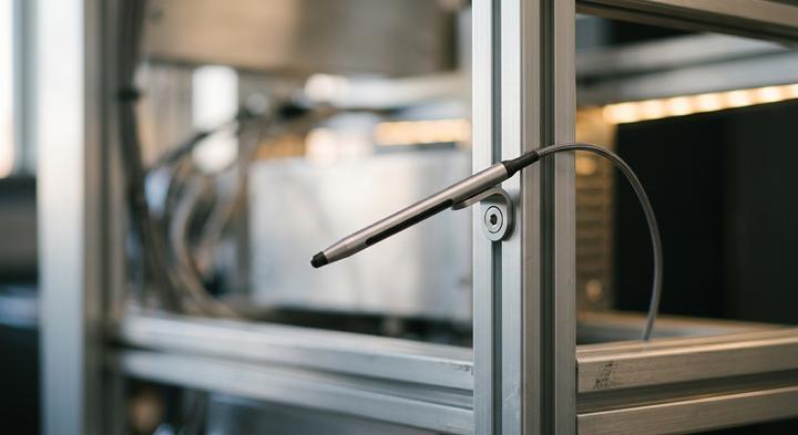
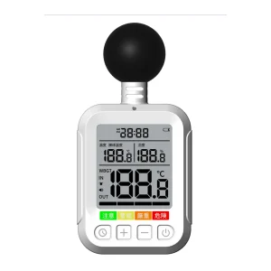
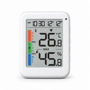
Custom-molded, sub-6mm digital hygrometer nodes fit cleanly within restricted rack frame margins without obstructing airflows.
An operations team trying to zip-tie a bulky, three-inch plastic sensor probe into the tight two-inch margin of a crowded 30kW server rack quickly realizes that standard hardware doesn’t fit where the risk is. When you are upgrading a 120-rack Tier III facility running dense workloads, those physical margins are practically nonexistent. Standard auxiliary temp and humidity probes, usually tossed into the shipping box as cheap smart PDU accessories, are simply too thick to place in active air paths. Instead of measuring critical intake air, these rigid plastic blocks end up dangling in dead spaces or pushed out into the exhaust stream, remaining completely blind to the turbulent localized microclimates where cold-air floor delivery collides with high-velocity server fans.
The failure isn’t just about physical fit; it is a matter of sensor dynamics. Standard off-the-shelf sensors rely on thick, restrictive injection-molded housings. In a high-density setup running variable workloads, localized static pressure drops can pull hot exhaust air backward through an adjacent idle chassis, creating rapid microclimate shifts. To catch these fluctuations before they trigger hardware alarms, a custom digital hygrometer node is required. Rather than forcing generic parts to fit, a manufacturer like YGhao can shrink the housing down to a slim, low-profile footprint that slips directly into the narrow sheet metal channels of the rack frame. Customizing both the housing geometry and the sensor calibration parameters ensures you measure the true boundary layer air entering the server, rather than the diluted ambient air inches away.
In a Tier III facility operating under strict uptime SLAs, relying on average aisle humidity is an expensive gamble. A single unmonitored humidity pocket can quietly trigger microscopic copper dendrite growth on high-density motherboard traces, causing a short before the main room-level system registers a change. When retrofitting dense cabinets, a solid rule of thumb to bring to your next engineering meeting is to reject any probe housing thicker than 6 millimeters—anything larger disrupts the very boundary airflow you are trying to monitor, masking the localized condensation risks that cause silent, multi-node failures.
Defining Custom Sensor Node Specifications: Core Hardware Benchmarks
How do you specify a custom digital hygrometer node that won’t drift under high-velocity airflow?
In high-density 30kW+ cabinets, standard analog drops run parallel to high-voltage PDU rails behave like antennas, soaking up electromagnetic noise that ruins relative humidity calibration. To block this interference, experienced facility leads mandate shielded RS-485 Modbus RTU digital communication over raw analog lines. Furthermore, the physical node must slip into cabinet channels using a custom-molded enclosure under 6mm thick so it never blocks boundary layer airflow or pinches fiber bundles against the glass doors.
| Buyer Type | Sensor Core | Enclosure Airflow Profile | Drift Limit | Hysteresis Buffer | Unit Cost | Primary Risk & Verdict |
|---|---|---|---|---|---|---|
| Tier III/IV Colocation (30kW+ High-Density Racks) | Sensirion SHT4x | Custom 6mm ultra-thin molded polymer | < 0.25% | ±1.0% | High tooling amortization | Electromagnetic interference from high-voltage lines; Verdict: Standardize on custom-molded shielded digital nodes. |
| Modular Edge Containers (Unattended Pods, 10-15kW) | Bosch BME core | Low-profile bracket with integrated venting | < 0.50% | ±1.5% | Moderate component cost | Dust accumulation in unattended environments; Verdict: Choose IP50-rated custom housings with protective PTFE dust vents. |
| Legacy Enterprise Rooms (Low-Density, <5kW Racks) | Tier-2 sensor core | Standard 15mm snap-on housing | < 1.00% | ±2.0% | Low initial unit cost | Blocked door clearance and cable pinching; Verdict: Reject analog drops for any runs exceeding 2 meters. |
Commercial Specifying Verdict
Balancing custom tooling costs against long-term sensor drift is a basic lifecycle equation: paying more upfront for a high-stability Sensirion core protects your SLA far better than sending techs to manually recalibrate cheap, unshielded nodes every six months. YGhao’s engineering team handles the thin-profile plastic injection molding and sensor integration directly to bypass vendor-stack compatibility issues. For long-term reliability in high-density environments, treat any run over two meters as a non-negotiable candidate for shielded RS-485 digital output rather than analog drops.
Adapting Custom Sensor Architectures to High-Density Thermal Zones

Mapping thermal boundary zones helps locate sensor probes directly in active intake air paths.
When an engineering lead unboxes a standard 15mm plastic sensor probe on a Monday morning, the realization hits: it is simply too thick to fit anywhere near the intake vents of a 30kW cabinet without choking the airflow. If you are retrofitting these high-density setups, the physical architecture of the rack dictates how your environmental telemetry behaves under actual load.
Density Containment: Overcoming Airflow Boundary Obstructions
In cold-aisle containment layouts, the primary engineering challenge is reading the entry air temperature and relative humidity directly before it touches dense blade arrays. If the sensor housing is too bulky, it alters the local boundary layer, skewing the calibration and masking localized hot spots. Slipping a custom digital hygrometer with an ultra-thin sub-6mm probe directly into the structural door frame channels avoids this physical interference. For these layouts, using flat magnetic mounts rather than drilling preserves cabinet integrity while placing the sensor elements exactly in the path of the incoming microclimates.
Air Hybrid Pods: Preventing Condensation Disasters
Retrofitting high-density GPU clusters often introduces a mix of liquid and air cooling where condensation on cold manifolds is a constant threat. Drilling into copper lines to insert inline sensors is a guaranteed way to void a cooling system warranty, but waiting for room-level alarms is too slow. For these Air Hybrid Pods, a more reliable safeguard is mounting dual-zone customized probes directly to the rack-frame edge, complete with localized visual LED indicators. This provides a direct physical warning to onsite staff on the aisle floor the moment dew points creep toward condensation limits, long before the centralized DCIM system processes the network telemetry.
Sealed Edge Enclosures: Climate Monitoring Without Active Airflow At the Edge
Sealed, fanless edge cabinets present a different challenge: without active circulation, stagnant air traps localized humidity, making them highly sensitive to external weather shifts. Running dedicated communication lines to hundreds of these remote sites is economically impractical. The standard workaround is daisy-chaining Modbus RTU nodes configured with custom RJ45 pinouts over existing infrastructure. This custom pinout allows engineers to utilize spare utility lines within the pre-existing rack cabling, feeding environmental data directly to the central DCIM without the cost of pulling new physical runs.
When writing your next sensor RFQ, always specify the maximum cable bend radius and housing thickness as hard constraints—otherwise, you risk buying highly accurate hardware that physically cannot clear the cabinet door.
Sourcing Pitfalls That Lead to Premature Sensor Drift and Failure

True sensor stability relies on thermal isolation and routing cutouts on the custom PCB to prevent self-heating drift.
Sourcing a custom digital hygrometer that survives a high-density data center run is about physical board layout and probe protection, not the brand of the sensor chip. When analyzing field failure, sourcing teams usually discover that raw spec sheets mask major integration flaws. If a factory mounts a premium Swiss sensor but ignores PCB-level thermal isolation, the node’s readings will drift out of tolerance within days of deployment.
High-end raw sensor chips guarantee long-term accuracy regardless of internal board design.
Placing a tier-one Swiss sensor chip on a poorly engineered, self-heating internal PCB defeats its factory calibration within hours. When a microcontroller or power regulator sits too close to the active sensing traces, local thermal dissipation skews the relative humidity reading by heating the air surrounding the die. Sourcing engineers must verify that the manufacturer physically isolates the sensor element using thermal relief slots, routing cutouts, and physical board air gaps to keep parasitic thermal transfer below 0.1°C.
Unfiltered sensor heads are perfectly fine for clean, air-conditioned data center environments.
Even in filtered data halls, high-velocity airflow carrying sub-micron particulates, vaporized lubricants, and trace aerosols will bombard an unprotected capacitive sensor element. Omitting a hydrophobic, dust-proof PTFE filter membrane leads to rapid particulate deposition on the active polymer layer. Over months of continuous draft exposure, this layer clogs, preventing proper moisture exchange and causing the sensor’s calibration curve to drift permanently from a nominal ±1.5% RH down to ±5% RH or worse.
Macro-level ambient room telemetry will catch localized rack-level humidity spikes.
Macro-level room monitoring completely misses the intense localized microclimates generated inside high-density 30kW cabinets, especially near hot-aisle exhaust zones. When sensors are subjected to persistent 45°C+ dry exhaust drafts, their polymers degrade unevenly compared to the cooler intake zones. Unless you specify localized, rack-level probe placement paired with protective porous filters, your environmental monitoring system will report healthy room-wide averages while individual node tolerances quietly drift out of SLA compliance.
Humidity sensor drift is a slow, predictable decay that stays within manageable limits over five years.
Vetting Environmental Sensor Manufacturers: Audit Protocols and Certifications
Specifying a shielded RS-485 Modbus RTU node with a sub-6mm enclosure profile looks great on a CAD layout, but those boundaries only protect your data center if the factory actually builds what they promise. Buyers often focus on design Certifications While ignoring the physical assembly line where accuracy is actually won or lost.
| Audit Focal Point | Requested Documentation | Common Red Flag | Factory Verification Method |
|---|---|---|---|
| Calibration Traceability | Active NIST or ISO/IEC 17025 master reference probe certificates; chamber testing logs showing serial-by-serial accuracy curves. | Presenting self-certified PDF sheets without matching master serial numbers or real-time temperature/humidity step logs. | Inspect calibration chambers on-site or via live video; verify master reference probe calibration dates and physical serials. |
| Infant Mortality Screening | 48-hour continuous burn-in chamber logs; historical yield charts showing post-test failure rates for recent production lots. | Direct packing from SMT assembly lines to shipping boxes without environmental stress testing or voltage-variation testing. | Trace completed production units back to their specific burn-in run sheets, chamber power logs, and operator signatures. |
| Enclosure Tolerance | IP rating lab reports (IP65/IP67); physical measurement logs for the custom digital hygrometer shell; tooling maintenance schedules. | Housing dimensions varying beyond ±0.1mm; lack of physical cable strain relief test records or drop-test documentation. | Audit tooling calibration logs; witness a physical caliper/CMM check on five random units pulled straight from the line. |
| Sensor IC Sourcing | Original manufacturer (e.g., Sensirion, Bosch) certificate of conformity; incoming quality control (IQC) inspection logs. | Inability to provide direct trace documents back to authorized silicon distributors; unusually low unit prices for high-spec ICs. | Inspect IQC storage conditions and verify packing slip batch numbers match the active production run tracking sheets. |
Verifying Calibration Integrity
Relying on a static PDF datasheet to guarantee sensor accuracy is a fast way to drift off-spec within months of deployment. True validation requires looking at the actual factory process: are they putting the fully assembled custom digital hygrometer units through environmental chambers, or are they just calibrating the bare PCBs before potting? We have seen sub-tier factories run Infant Mortality Protocols Relying on nothing more than letting the boards sit on a room-temperature bench for an hour. To avoid this, demand to see the thermal cycling records and ask if their standard QC includes YGhao’s 48-hour burn-in chamber run; if they stall or claim that self-certified sheets are enough, they are likely cutting corners on the chamber time.
Planning Your First 50-Node Custom Sensor Pilot with YGhao
Now that the electrical noise benchmarks and the 0.25% maximum annual drift limits are written into the spec sheet, the next practical step is proving these tolerances in a live, high-EMI cabinet environment. Moving straight to a site-wide deployment without running a localized Node Custom Sensor Pilot is a recipe for expensive cable-routing surprises and packet collisions. Isolating a 50-node trial to a single high-density cabinet row allows your team to stress-test polling rates, verify RS-485 Modbus RTU communications, and fine-tune physical clearance limits before releasing the full PO. YGhao supports this pilot by customizing the physical and electrical interfaces directly at our Shenzhen facility: we pin out RJ45 or USB connectors to your exact controller assignments, color-code wire jackets to match your facility’s safety standards, and supply custom cabling harnesses trimmed to the exact rack footprint to prevent air-blocking slack loops. By modifying these parameters during manufacturing, the physical nodes slide straight into the restricted 6mm channels of your existing rack frames without requiring on-site cutting or tedious manual field crimping.
To keep the deployment moving without field delays, we maintain a strict boundary on the division of labor: our factory delivers calibrated, bracket-mounted hardware built to your specs, but we do not handle local electrical contracting, conduit installation, or physical cable pulls. Your local union or certified electrical contractor handles the physical site integration, while our engineers guarantee that every sensor meets physical dimensions and electrical continuity before shipping. This setup avoids typical finger-pointing when the physical installation begins. To get your contractor started on the bracket layout and cabling runs before the pilot hardware lands, our engineering desk can provide verified CAD models and terminal pinout templates. Email our engineering team directly to request the DXF or DWG mounting drawings for your custom rack bracket layouts, and we will package the files alongside the electrical wiring templates within one business day.