Hardware Sourcing 101: Selecting the Right Factory for Your Custom Digital Hygrometer
The First Month in the Field: Why Custom Digital Hygrometers Drift and Fail
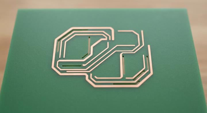
Physical isolation on the PCBA prevents heat transfer from active components to the sensor.
The pristine ±2% relative humidity (RH) rating on a component’s datasheet is a complete fiction the moment that sensor is sealed inside a finished product enclosure. Sourcing teams routinely award bulk manufacturing contracts based on these laboratory-grade specs, only to watch field-failure rates spike during the first thirty days of an industrial IoT deployment. Once a sensor is trapped inside a tight, unvented plastic housing, restricted airflow and stagnant air drag its real-world performance down to a sluggish ±8% RH. The mistake is treating a physical integration problem as something you can easily calibrate away later.
These early field failures almost always boil down to two physical design blindspots: chemical drift and thermal bleed. Standard factory adhesives, epoxies, and cheap potting compounds outgas volatile organic compounds inside the sealed housing, permanently poisoning the polymer-based sensor element. At the same time, routing high-power PCB traces or voltage regulators too close to the sensor creates a local microclimate. This thermal bleed fakes dry conditions that have nothing to do with ambient reality. Trying to fix this with software offsets is a temporary patch; as the enclosure chemistry and board components age, those software corrections inevitably fail.
A reliable manufacturer like YGhao solves this on the factory floor with structural isolation, not code. This means designing physical airflow vents into the housing, routing physical isolation slots directly into the PCBA to block heat transfer, and specifying certified low-outgassing assembly adhesives. When negotiating with an OEM/ODM supplier, skip the generic quality assurance slides and ask for their CAD files. If they cannot point to physical isolation slots and clear venting paths on the 3D model, do not trust their software offsets to prevent long-term field drift.
Core Selection Benchmarks: Comparing Sensor Precision, Communication Interfaces, and Ingress Protection
Which hardware specifications actually prevent field drift when sourcing a custom digital hygrometer for high-reliability industrial use?
Selecting the correct mix of physical sensor elements, communication buses, and ingress protection ratings dictates whether a custom digital hygrometer survives in the field. Sourcing teams often specify nominal datasheet accuracy while ignoring how moisture, dust, and electrical interference degrade performance over time. Balancing these trade-offs requires aligning electrical interfaces and housing specifications to the exact environmental stressors of the application.
| Application Environment | Sensor IC Type | Interface & Filtering | Venting & IP Spec | Primary Failure Mode |
|---|---|---|---|---|
| Cold Storage (Condensation cycles) | Bandgap with protective layer | I2C, pull-up resistors & RC filter | IP67 hydrophobic PTFE | Saturation lock-up or sensor drift |
| HVAC Ducts (High air velocity, dust) | Polymer with high tolerance | Modbus RTU (RS-485), TVS diodes | IP65 sintered bronze mesh | Particulate caking & 40s lag |
| Chemical Processing (Solvents & VOCs) | Glass-substrate bandgap IC | SPI with differential line drivers | IP54 with carbon filter | Chemical dielectric poisoning |
Engineering Around Sensor Lag, Chemical Drift, and Bus Corruption
Choosing between polymer capacitive and bandgap semiconductor elements is a critical architectural decision. Polymer elements rely on a porous dielectric layer to absorb water vapor. While highly sensitive, they are vulnerable to volatile organic compounds (VOCs) and solvents that permanently bind to the matrix, causing irreversible drift. In environments with heavy chemical exposure, specialized glass-substrate bandgap ICs are superior; they measure humidity via micro-machined semiconductor junctions, bypassing organic polymer vulnerabilities.
Protecting digital buses from electrical noise is vital when routing I2C or SPI signals over external lines. Standard I2C is an open-drain bus sensitive to parasitic capacitance; runs over 30 centimeters can round off signal lines and trigger lock-ups. To prevent this, the PCBA must integrate optimized pull-up resistors (dropping from 10kΩ to 2.2kΩ) and localized RC low-pass filters (a 100Ω series resistor and a 100pF capacitor to ground) near the pins. At YGhao, we systematically model line impedance during layout design to guarantee data integrity.
Physical protection also introduces measurement lag. Hydrophobic PTFE membranes block water and dust down to the sub-micron level, but they trap a micro-climate over the sensor chamber, increasing response times ($T_{63\%}$) from 4 seconds to over 30 seconds. Conversely, sintered bronze filters resist high-velocity dust in HVAC ducts but clog easily in oily environments. Sourcing teams must prioritize these dynamics during RFQ alignment to prevent field control-loop delays.
Application Scenarios: Solving Complex Integration Challenges with Custom Enclosures
A QC engineer inspecting a returned batch of environmental loggers knows immediately when a standard housing has failed: the relative humidity reading has locked at 100% and refuses to budge. Standard sensor housings are built for static laboratory air, not the rapid velocity shifts, localized board temperatures, and outgassing chemicals found in active industrial environments. When integrating a custom digital hygrometer into high-reliability hardware, the enclosure cannot be treated as a simple plastic box; it is an active mechanical buffer that must shield the sensitive polymer element from the surrounding system’s self-generated microclimate.
Cold-Chain Shipping: Handling Rapid Condensation and Hermetic Seals
When shipping biologics across varying climate zones, rapid temperature transitions cause moisture to condense instantly on cold internal surfaces. Some suppliers try to achieve Hermetic Seals When they pour generic potting resin over the entire PCBA. This exposes the device to The Potting Trap: standard epoxies release volatile organic compounds (VOCs) as they cure and age inside airtight spaces, permanently degrading the sensor’s polymer layer. For reliable Chain Shipping performance, the sensor element must be physically isolated from the potted cable-entry using a dual-chamber enclosure with a mechanical silicone seal, allowing the sensor to breathe through a selective hydrophobic membrane rather than swimming in condensate.
Data Center Exhaust: Tracking Low-Humidity Microclimates and Localized MCU Heat
Monitoring containment aisles or server rack exhaust means Tracking Low humidity zones that frequently drop below 15% RH. In these dry environments, even minor localized thermal offsets ruin the sensor’s accuracy. If the onboard microcontroller dumps Heat In nearby copper traces, that thermal energy migrates directly to the sensor. To stop this, we specify physical air-gap isolation slots—often called Copper Keep-outs—that isolate the sensor element onto its own circuit board island. Eliminating this internal thermal bridge is the only way to prevent the sensor from reading an artificially depressed relative humidity level caused by the surrounding electronics.
Industrial HVAC Ducts: Defending Against Chemical Spray and Particulate Cake
In commercial HVAC systems, duct-mounted sensors face a continuous onslaught of washdown chemicals and heavy airborne dust. Without proper mechanical shielding, a thick Particulate Cake builds up on the sensor mesh, slowing response times from seconds to minutes. While simple plastic caps fail quickly, Defending Against Chemical Spray requires a sintered stainless steel or porous PTFE filter housing that resists aggressive sanitizing agents. When sourcing duct sensors, a good rule of thumb is to specify sintered metal for high-velocity particulate streams, but switch to membrane filters if the duct undergoes regular chemical misting.
Sourcing Pitfalls: Why Treating Custom Digital Hygrometers as Commodities Causes Early Field Failures
Procurement mistakes, rather than raw component defects, account for nearly all custom digital hygrometer field failures. When buying teams evaluate ODM suppliers solely on raw silicon datasheets, they miss the system-level integration risks that cause drift in the wild. If the housing geometry, board thermal paths, and post-assembly recovery are not matched to the sensor element, even a premium transducer will produce erratic, out-of-tolerance readings.
“If the sensor datasheet says ±2% RH, we will get ±2% RH in our final molded housing.”
This assumption ignores the micro-climate created inside a real product enclosure. Placing a custom digital hygrometer close to power regulators or microcontrollers creates localized warm zones. A temperature spike of just 1°C inside the housing drops the local relative humidity by approximately 6% at ambient room conditions. No sensor bypasses the laws of physics. If your supplier does not demand a system-level airflow and thermal review of the CAD files before cutting tooling, you are designing a permanent offset error into your hardware.
“Our software team can easily program a flat offset to correct any sensor errors post-assembly.”
Relying on a static software patch assumes humidity drift is linear, which it never is. While a simple flat calculation might make the device look accurate at 40% RH on a test bench, it falls apart as soon as the unit encounters environmental extremes. Near high condensation levels at 90% RH, or during dry spells down to 10% RH, polymer-based sensor membranes exhibit non-linear hysteresis. A hardcoded offset that works in the mid-range will either miss critical industrial control thresholds entirely or trigger false alarms at the margins.
“We can compress the production schedule by having the factory ship completed PCBAs immediately after they exit SMT reflow.”
This is the classic post-reflow blind spot. High-temperature reflow soldering bakes all the natural moisture out of the sensor’s capacitive polymer membrane, shifting its baseline. Skipping the mandatory 48-hour hydration recovery step—where the boards must sit in a controlled humidity chamber—leaves the sensors permanently dry-biased and prone to slow calibration drift. If a supplier promises to shave three days off your lead time by packing boards straight off the conveyor, they are selling you assemblies that are essentially broken out of the box.
Are you ready to ask your manufacturing partner to detail their post-reflow stabilization protocol before you sign off on the tooling?
The Factory Audit Checklist: Verifying Calibration Chambers, Traceability, and Post-Reflow Recovery

Rigorous environmental chamber testing ensures sensor accuracy across the full range.
How do you verify that a custom digital hygrometer factory actually builds to the specifications promised on their datasheet? Paper certificates are easy to forge, but the real indicator of field reliability is the physical calibration equipment and post-assembly hydration disciplines active on the factory floor.
Assembly Audit Metrics
| Audit Area | Verification Objective | Physical Evidence | Red Flag / Quick Rejection Sign |
|---|---|---|---|
| Chamber Calibration | Verifying Calibration Chambers are traceable to NIST, DAKKS, or JJF national standards. | Active calibration certificates with matching serial numbers of the chamber controllers. Look for a minimum of 3-point calibration curves covering the sensor’s range (e.g., 10%, 50%, and 90% RH at 25°C). | Calibration stickers that are missing, hand-written, or expired. No proof of an active chilled-mirror reference standard. |
| Post-Reflow Hydration | Reflow Recovery How: Confirming the factory runs a mandatory 48 hours high-humidity recovery step to rehydrate the sensor’s active polymer after SMT reflow. | Dedicated chambers holding 75% to 85% RH at 25°C. Audit physical batch traveler logs and automated environmental tracking records to prove each PCB lot dwelled for a full 48 hours. | PCBA boards routed directly from the SMT reflow conveyor to final assembly, skipping the recovery phase. A supplier claiming ambient room humidity is sufficient. |
| Tooling & Enclosure (FAI) | Check first-article inspection (FAI) records for elastomer gasket compression and sonic-welded seams. | Cross-sectional CAD analysis showing target compression of the silicone seal (30% to 40%). Physical FAI reports with micrometer measurements and pressure-leak decay testing records. | Molded enclosures showing uneven gaps, flash along ultrasonic weld lines, or gaskets that lack specified compression depth. |
Skipping these physical checkpoints introduces systemic quality risks that no software offset can fix. For example, bypassing the 48 hours polymer hydration step means the custom digital hygrometer units ship in an artificially dry state, causing them to drift by as much as 5% to 8% RH during their first month in service as they pull moisture from the environment. Similarly, uncalibrated reference chambers compound errors down the entire production line, turning a typical ±2% specification into a ±5% reality before the shipment even leaves Shenzhen. Auditing these physical steps on the shop floor, rather than reviewing PDF certificates in a conference room, is what separates a reliable industrial partner like YGhao from an assembly line cutting corners.
Moving from Specifications to Physical Pilot: Securing Accuracy with YGhao’s Engineering Run
Now that physical isolation slots and custom chamber calibration models are on paper, the immediate engineering challenge is verifying how these variables collide in a live enclosure. A datasheet might promise an absolute accuracy of 1.5% RH at the sensor component level, but it can never calculate how a minor route variance on your PCBA or a microscopic restriction in the venting pathway will restrict local airflow. Jumping straight from a 3D CAD render to high-volume injection tooling is where hardware margins go to die. If your prototype’s processor runs just 2°C hotter than the thermal simulation predicted, or if the selected sensor membrane retains a tiny pocket of stagnant humidity, your baseline calibration is ruined. Discovering a structural offset like that after you have cut steel injection molds will cost upward of $20,000 in tooling modifications and delay your product launch by three months. Setting up a Physical Pilot of 10 to 20 units is the only way to safeguard your unit economics and ensure the device performs reliably in the field.
Our focus is strictly on custom PCBA layout design, specialized plastics, and factory multi-point calibration for industrial OEMs, rather than mass-producing wholesale consumer goods. This means our engineering team works directly with yours to align housing layouts with existing mechanical envelopes, optimize airflow, and manage thermal isolation on the board. Running a physical, low-volume trial through our dedicated Engineering Run Now program gives you the exact physical data needed to test for micro-climates and structural drift. To begin Securing Accuracy before committing your tooling budget, you can download our complete package of reference STEP files and design templates, or send your raw Gerber files directly to our engineering desk for a preliminary review and a pilot-run quote.