Mitigating Risk on Your First Custom Thermo-hygrometer Batch: Tooling and pre-PO Checks
The Hard Cost of Tooling Blind: Why Your First Custom Thermo-hygrometer Batch Needs Pre-PO Guardrails
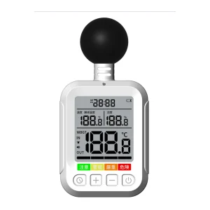
An accurate thermo-hygrometer reading is almost always ruined by a sleek retail housing. While industrial buyers prioritize heavy-walled, rugged casings designed for harsh warehouse floors, retail brands focus on ultra-thin bezels, high-clarity LCD view angles, and a compact footprint that sits cleanly on a store shelf. This cosmetic focus, however, creates an unintended microclimate trap inside the device. When you seal a plastic casing to achieve a continuous, unbroken aesthetic, you choke the ambient airflow. The internal sensor sits in a stagnant pocket of dead air, lagging behind ambient room changes by hours while absorbing heat from the display’s own battery and circuitry.
The first 30 days of mold planning are the only phase where correcting these thermal and structural imbalances costs nothing. Once a CNC machine starts cutting tooling-grade steel, adjusting a misplaced ventilation path or isolating a drifting sensor chamber means thousands of dollars in wasted mold modifications and months of missed market windows. To avoid this, technical CAD audits must treat the housing as an active instrument component rather than just a cosmetic shell. YGhao acts as both a mold designer and instrumentation lab, auditing technical CAD files before physical tooling starts to analyze plastic melt flow, structural tolerances, and sensor chamber isolation simultaneously.
An extra 0.5-millimeter shift in a mold gate or a relocated vent is simple to execute on a screen, but impossible to adjust on a hardened steel core without scraping the run. The safest rule of thumb before signing any purchase order is to make your supplier prove sensor isolation with a formal airflow simulation.
Specifying the Shell: Tooling Paths, PCB Space, and Case Vent Trade-offs
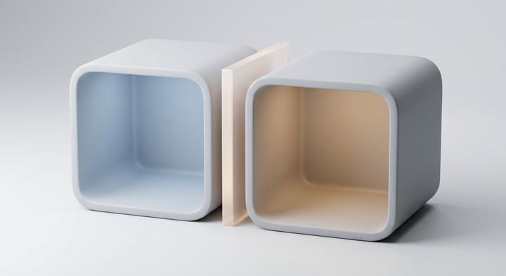
Conceptual diagram of sensor chamber physical isolation to block heat radiation.
Which tooling path balances upfront mold costs and per-unit margins for a custom thermo-hygrometer?
If you are shipping fifty thousand retail units a year, there is no way around custom tooling. But if this is a pilot run of a thousand industrial devices, writing a check for a custom mold is a fast way to kill your working capital before your board design is even stable. When evaluating different Tooling Paths, you are balancing upfront development liquidity against long-term unit cost margins.
| Tooling Path | Upfront Tooling Cost | Sample Lead Time | Design Flexibility | Unit Cost Margin Impact |
|---|---|---|---|---|
| Fully Custom Injection Mold | $12,000 – $25,000 | 45 Days | Maximum: Complete control over sensor chamber isolation, custom ventilation slot geometry, wall thicknesses down to 1.2 mm, and customized internal mounting bosses. | Highest Long-Term Margin: Low material-only unit costs; amortization occurs over 20,000+ units, making it ideal for competitive retail markets. |
| Modified Off-the-Shelf | $1,500 – $4,000 | 20 Days | Restricted: Stock enclosure profiles only. Customizations are limited to precise CNC milling for sensor windows, connector ports, and custom silk-screened branding elements. | Moderate Margin: Elevated per-unit base cost due to machining time and fixture setup amortizations, which increases unit cost by 25% to 40%. |
| Open-Mold (Standard Shell) | $0 | 10 Days | None: Fixed physical dimensions and predetermined venting configurations. The internal printed circuit board (PCB) must be engineered entirely around the existing cavity. | Lowest Margin: Premium wholesale casing prices apply; lacks physical brand differentiation on store shelves, exposing the product to direct copycat competition. |
Microclimates, Alignment Fixtures, and the True Cost of Setup
Selecting a path is only half the battle. A common engineering trap we see at YGhao is ignoring how plastic wall thickness and battery proximity alter internal physics. If your wall is a thick 1.2 mm but you fail to isolate the sensor chamber, heat from the battery or microprocessor will pool inside. This creates localized microclimates that skew relative humidity readings by up to 8% and temperature by 2°C.
Furthermore, the “zero-dollar” open-mold path often hides setup costs. You might avoid a mold fee, but you will pay for custom silk-screening jigs, manual alignment fixtures for the PCB, and bespoke vacuum-formed retail packaging trays because standard cases rarely fit standard packaging. Navigating the Case Vent Trade requires calculating these hidden pre-production steps before committing to a tool.
From 3D CAD to First Physical Plastic: The 30-Day Tooling and Prototype Check
Pulling the first T1 shot off an injection press is where digital simulation meets physical reality. Transitioning from a STEP file to a calibrated housing requires a strict 30-Day Tooling workflow. The first week focuses on gate-location mold-flow analysis to prevent sink marks around venting slots. By week two, core and cavity steel are cut, aiming for T1 trials by day twenty. During this critical Prototype Check The toolmakers inspect tolerances, surface finishes, and draft angles to confirm the plastic flows correctly without warping. The remaining ten days resolve tolerance stack-ups and physical testing before final sign-off. If a vendor offers to compress this to save five days, they are usually cutting corners on the trial runs, which almost always guarantees assembly issues on the final line.
Scenario A: The Styling-Focused Desktop Display
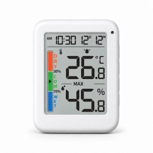
Focused Desktop Display When designing a wide-format LCD thermo-hygrometer with a magnetic wall mount, the major risk is heat build-up behind the display. The Styling often demands a completely sealed rear housing to keep the cosmetic lines clean, but backlights generate constant, low-level heat. If that heat is trapped, it skews the sensor’s accuracy. During a pre-tooling CAD audit, we analyzed a casing where trapped backlight warmth raised internal chamber temperatures by up to 2.2°C. Instead of cutting steel immediately, the solution was to route a hidden perimeter vent path along the magnetic mounting recess. Catching this during the week-one simulation phase allowed us to modify the core geometry before CNC milling, protecting both the aesthetic and the sensor calibration.
Scenario B: The Compact Smart-Home Sensor
The Compact Smart Home Sensor For Wi-Fi or Bluetooth deployments faces a different heat source: radio transmissions. Every time the active antenna transmits, it creates brief localized thermal spikes that depress local relative humidity readings. This cannot be reliably compensated for in code because ambient airflow is highly variable. At YGhao, we isolate the sensor chip physically. The 30-day milestone timeline includes validating thin internal rib barriers that partition the sensor into a separate, isolated atmospheric chamber. This keeps the transceiver’s heat on the opposite side of the PCB, venting it out through small dedicated exhaust slots. Designing physical isolation into the housing is the only way to avoid chasing software offset bugs after the product is in the field.
Three Tooling Mistakes That Cause Thermal Lag and Sensor Calibration Errors

Proper ventilation design ensures natural airflow reaches the sensor without stagnation.
Physical housing design dictates real-world sensor accuracy far more than the chip’s nominal datasheet. Sourcing teams spend weeks comparing sensor chips, but a poor casing ruins that accuracy on day one. Poor mechanical execution in the shell guarantees Sensor Calibration Errors Three months into a production run. To avoid scrap and field failures, you must analyze the thermodynamic trade-offs of the enclosure before signing off on the tooling PO.
Myth: Any standard plastic factory can mold a thermo-hygrometer case as long as they have a basic 3D STEP file.
Most injection molders optimize for fast cycle times and cosmetic perfection, meaning they instinctively thicken walls to prevent cosmetic sink marks. In a thermo-hygrometer, thick plastic walls behind the sensor cavity act as an unintentional heat sink. This thermal mass slowly absorbs and releases ambient heat, creating severe lag. To prevent this, design thin-walled sensor chambers constrained to 1.0 to 1.2 mm. Insist that your tooling partner runs a mold-flow analysis targeting cooling rates inside the sensor chamber before any steel is cut.
Myth: Venting slots can go anywhere on the housing as long as they let some air inside.
Aesthetic vent placement regularly traps stagnant air, turning the internal chamber into an isolated microclimate. Placing vents only on the back or bottom for cosmetics stops airflow across the sensor entirely. This lack of natural convection produces a +1.5°C thermal lag when the device enters a new room, rendering it useless for responsive climate tracking. Real-time accuracy requires a vertical chimney effect: air must enter near the bottom, flow across the sensor, and exit through top vents. Check your CAD model for a clear convective path rather than relying on a supplier’s promise of ‘adequate venting’.
Myth: We don’t need complex internal isolation because we can fix any temperature error with a static software offset.
Software calibration offsets only resolve linear, static errors. They are useless against the dynamic, non-linear heat generated by your own electronics. When a thermo-hygrometer runs its wireless transmitter, backlight, or charging circuit, internal temperatures spike dynamically. This self-heating bleeds directly into the sensor chamber without an airtight physical barrier inside the housing. A simple offset cannot predict these shifts under varying battery loads. You need physical walls molded directly into the case to seal the sensor away from the PCB. Is your supplier ready to run a thermal mold-flow simulation before you wire the tooling deposit?
The Factory Calibration and Mold Audit: What to Demand Before Cutting Steel
How do you verify a custom thermo-hygrometer manufacturer’s calibration capability before cutting steel?
A printed certificate of conformity doesn’t mean the factory can actually calibrate an instrument. Anyone with a laser printer can produce a compliance sheet. To avoid a costly tooling rework after the steel is hardened, you must audit the supplier’s molding competency, simulation files, and calibration standards before signing off on the tooling PO.
| Audit Checkpoint | Required Factory Proof | Supplier Red Flag | Department Owner |
|---|---|---|---|
| Molding Competency | Internal mold-flow reports and thermal-dissipation analysis before cutting core and cavity plates. | Refusal to share flow simulations or gate-location plans. | Mold Engineering |
| Calibration Chamber | Live multi-point chamber logs showing dynamic humidity and temperature sweeps. | Relying on single-point handheld master meters for factory proof. | Quality Assurance |
| Sign-off Milestones | Written protocol separating physical T1 fit from functional T2 calibration approvals. | Demanding mass-production deposits before physical T1 sample sign-off. | Procurement / Purchasing |
Molding Proof Points
A thermo-hygrometer housing is more than a plastic cover—it behaves like a micro-climate chamber. If the case design doesn’t isolate the internal sensor from the heat radiating off the PCB, backlight, or lithium battery, your readings will be systematically skewed. A qualified manufacturer runs mold-flow and thermal-dissipation analysis before machining the core and cavity plates. When we audit designs at YGhao, we verify the air vectors inside the shell to ensure ambient airflow reaches the sensor without picking up localized board heat. If a supplier cannot show you these airflow models, the physical tool will likely lock in a permanent thermal offset.
The calibration setup is where low-cost factories cut corners. A single-point factory certificate only tells you the device read correctly under one static clean-room condition on a random Tuesday. Real-world accuracy requires multi-point environmental test chamber verification. Demand to see the raw logs of their calibration chambers executing dynamic sweeps—specifically running humidity ramps from 20% to 90% RH and temperature steps. If their lab relies on basic handheld reference meters for rapid spot checks, they are building consumer novelties, not precision instruments.
To protect your budget, keep engineering and purchasing aligned with clear milestones. Do not release mass-production funds until you have physically qualified the T1 and T2 samples. The T1 gate must lock down structural tolerances and tool venting, while the T2 gate verifies actual calibration performance under environmental stress. It is a simple division of labor: purchasing owns the commercial release, while the technical team owns the physical proof points.
Securing the Production Run: The Final Checklist and RFQ Sign-off
Once the vent trade-offs are settled and the pre-production tooling paths are locked in, the focus shifts to turning those hand-carried prototype victories into a predictable, high-yield Production Run. The reality of thermo-hygrometer manufacturing is that physical tooling design completely dictates final instrument accuracy. Saving a few hundred dollars on cheap mold sliders, simplified gate placements, or skipped core polishing is a classic trap; warped housing walls or misaligned seams will trap ambient heat and render the internal sensor useless, sparking thousands of dollars in retail returns. Keeping mold engineering and sensor calibration under one roof is how we prevent these field failures. Because we run our tooling division alongside SMT lines and calibration chambers, our designers can adjust the plastic shrinkage rates and structural draft angles to match the exact air-exchange demands of the SMT-mounted sensors. This alignment ensures that the fifty-thousandth retail unit performs identically to the initial design spec.
Rather than waiting for physical first-articles to fail their environmental chamber tests, you can use our engineering team to run a pre-tooling sanity check. Consider this the core step of The Final Checklist before your RFQ sign-off. Send your preliminary 3D CAD files (.STP or .STEP format) to us, and our engineers will perform a complimentary draft-angle and airflow optimization assessment. We will look for sink marks, parting-line risks, and thermal dead zones that could restrict airflow to the sensor. You will receive a straightforward, technical review—no sales push—showing exactly where the design is solid and where it risks failing, giving you the technical assurance you need before committing budget to hardened tool steel.