Launching a Custom Digital Clock on a Tight Budget: Finding Low-Risk Prototyping and Tooling Paths
The Real Cost of Injection Molds: Sourcing a Custom Digital Clock Enclosure Without Sinking Your Runway
Tooling strategy always dictates whether a custom digital clock enclosure actually makes it to market, long before the industrial design render is ever signed off. Hardware teams frequently spend months perfecting the sleek curves of a custom LCD display bezel, only to freeze when a toolmaker quotes a $15,000 upfront bill for a single-cavity steel injection mold. The common fallback—settling for cheap, off-the-shelf stock housings—is a slow-motion compromise that kills commercial appeal. It forces the engineering team to crop display dimensions, cram navigation buttons into awkward spots, and accept loose bezel tolerances that scream “prototype” to retail buyers. Even worse, 3D-printed prototypes hide these alignment errors; a desktop SLA print won’t warn you that a minor 0.2mm warp across a thin plastic rib will jam the high-speed pick-and-place nozzle during final assembly.
Mitigating this risk requires a staged tooling roadmap rather than an all-or-nothing capital bet. Experienced hardware teams look for manufacturing partners like YGhao that run both SMT lines and plastic injection molding shops on the same campus. This setup removes the classic vendor finger-pointing when the physical board doesn’t sit flush against the plastic bezel. Instead of committing to dedicated multi-cavity tooling on day one, developers can utilize modular insert tools and shared mold bases to defer thousands in upfront steel costs while the design stabilizes. Engineers can adjust the bezel aperture on a cheap insert to match real-world display offsets and component heights, aligning PCB layout changes with the tool design in real time before hard steel is cut.
This co-located approach solves the trickiest tolerance loop on a custom digital clock: the gap between the reflow oven and the injection gate. When a single factory handles both the SMT assembly and the enclosure molding, there is no room to blame the board house for component drift or the mold shop for sink marks. It is a practical way to achieve a tailored retail finish without exhausting working capital during the initial pilot runs. Never sign off on final mold steel until your supplier has run a sample PCB batch through the actual reflow oven to measure how much the board warps under heat.
Four Tooling Paths Compared: Keeping Custom Bezels and Display Glass Aligned
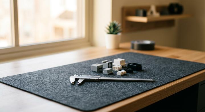
Achieving tight tolerances requires early physical verification and precise measuring tools during the prototyping stage.
If you cheap out on the front housing to save a few thousand dollars upfront, you will pay for it every single day on the assembly line. A mismatch of just 0.1mm or 0.2 mm between the molded plastic bezel and the display glass or diffuser isn’t just a cosmetic eyesore; it’s a mechanical disaster waiting to happen. When parts don’t sit flush, assembly operators have to manually wedge them into place, or use extra glue and heavy pressure to force a seal. The result is cracked cover glass, pinched gaskets, and high reject rates that completely wipe out whatever margin you thought you saved on the mold.
| Tooling Path | Target Buyer Type | Core Costs & MOQ | Alignment Tolerance | Primary Assembly Risk | Strategic Verdict |
|---|---|---|---|---|---|
| CNC-Milled Stock Enclosure | Startups doing functional validation | $0 mold fee; MOQ 100 | ±0.30 mm | Dust ingress and adhesive peel due to poor lens seating | Skip for retail; use only for low-risk industrial pilots. |
| Modular Insert Tooling | Mid-market B2B brands scaling up | $2,500 – $5,000; MOQ 500 | ±0.15 mm | Button sticking or binding at interchangeable plate seams | Cost-effective middle ground for moderate volume runs. |
| Hybrid Molds (Stock Back / Custom Front) | Specialized industrial OEM hardware | $4,000 – $7,000; MOQ 1,000 | ±0.10 mm | Uneven gasket sealing from dual-material shrinkage | Best for high-mix displays using a standard utility back. |
| Full Custom Tooling (Hardened Steel) | High-volume retail consumer brands | $8,000 – $18,000; MOQ 2,000 | ±0.05 mm | High upfront capital exposure prior to market testing | Mandatory for clean ±0.1mm light-guide alignment. |
Engineering the Alignment and Yield Trade-Offs
Let’s look at what actually happens when operators try to fix poor tolerancing. When you have a 0.2 mm gap on a CNC-milled display cutout, the operator’s natural instinct is to torque down the casing screws to force the housing closed. This transfers raw mechanical tension straight through the plastic boss into the FR4 board. Under that localized stress, the board flexes. That is where you get micro-cracked LCD driver pins, torn copper traces, or intermittent button-binding that only shows up after the clock is boxed and shipped.
At YGhao, we run our SMT lines and plastic injection shop under one roof to kill this exact problem. We don’t guess the tolerance stack-up; our toolmakers cut the bezel steel based on actual, post-reflow PCB warp profiles. If the board warps 0.1mm during reflow, we adjust the tooling’s internal alignment rib to compensate. This keeps the custom digital clock display glass aligned, holds the sealing pressure uniform, and prevents assembly stress from cracking your components on the line.
How Your Display Technology Dictates Enclosure Assembly (LED vs. LCD)
A tooling engineer spends hours modifying mold shut-offs on a Friday afternoon because a pre-routed PCB does not fit the drafted plastic standoffs. This headache is common when teams treat the housing as a simple box to be drawn up late. In reality, why routing your PCB layout before locking down your casing physical dimensions is a recipe for expensive layout revisions comes down to physical stack-up. Understanding How Your Display Technology directly Dictates Enclosure Assembly is what separates a clean snap-fit from a scrap bin of warped plastic; the choice between a reflective LCD and a hot-running LED panel dictates your PCB mounting standoffs, mechanical ribbing, and polymer shrink rate.
Segment LCD Consoles: Managing Low Volume Runs For Certification
For a medical diagnostic console using a segment LCD, production often involves low Volume Runs For early clinical testing of around 500 units. Since segment LCD consoles run cool, they do not need thermal vents, but their housings must still use flame-retardant PC/ABS to pass agency testing. To avoid sinking forty thousand dollars into dedicated steel tooling, the strategic path uses a modular master mold base with interchangeable cavity inserts. This allows the factory to modify the custom LCD window and button layouts while sharing a common back-shell tool. It reduces tooling lead times, bypasses the warpage of 3D prints, and minimizes certification costs.
Heavy-Duty Industrial Timers: Sealing IP65 Protection On The Shop Floor
On a concrete factory floor, a custom digital clock serves as an active heavy Duty Industrial Timers unit, constantly exposed to lubricants, high-pressure washdowns, and physical impacts. These rugged, low-volume builds demand a housing engineered for IP65 Protection On the shop floor. This means cutting a dedicated compression groove directly into the bezel to seat a custom elastomer gasket, paired with a thick-walled acrylic window. Unlike cold LCDs, high-brightness industrial LEDs generate concentrated heat inside a sealed chassis. If the enclosure does not feature localized heat-dissipation ribs molded directly behind the PCB standoffs, that trapped thermal load will rapidly degrade the LED brightness.
The ‘Tooling-Free’ Illusion: Mechanical Reality Checks in Low-MOQ Production
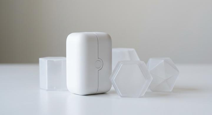
High-quality modular molding avoids cosmetic parting line variances and alignment gaps.
Secondary assembly labor is what actually kills the margins on a ‘tooling-free’ custom digital clock build. Many hardware teams bypass custom molding by using off-the-shelf casings, only to watch their unit economics fall apart during mass assembly. Understanding how these shortcuts impact physical tolerances is key to protecting your production budget.
Off-the-shelf enclosures are a cheap, plug-and-play way to bypass tooling fees.
Milling stock casings for a custom digital clock display window introduces ±0.4 mm of dimensional drift. That variance means your display glass sits crookedly or requires heavy manual glue chips to seal. What was supposed to be a quick shortcut becomes a high-scrap nightmare where cosmetic defects exceed 10% on the line. Utilizing a Production Secondary machining fixture or using modular tooling inserts with a manufacturer like YGhao keeps parts consistent without committing to a full custom mold.
3D-printed SLA resin is durable enough for end-use bezels in low-volume batches.
SLA photopolymers look clean on a desk, but they fail under real-world heat. A custom digital clock running high-brightness LED driver ICs continuously can easily reach internal enclosure temperatures of 55°C. At this level, standard SLA resins reach their heat deflection limits, causing the display bezel to warp, sag, or discolor. When the bezel deforms, the display window separates from its housing, letting dust and moisture in.
A standard open-cavity cover is sufficient to house a segment LED display.
Omitting molded interior isolation ribs means light from one segment of an LED digit bleeds into adjacent areas, making the display unreadable. Trying to manually glue die-cut foam gaskets inside a stock case to block this light-bleed is slow and error-prone. If the foam shifts even slightly, the defect returns. The internal geometry must be molded to seat flush against the PCB to isolate each light channel cleanly.
Digital CAD clearances are enough to guarantee perfect button travel and tactile feedback.
A 3D simulation cannot replicate the physical friction of plastic-on-plastic button travel under real tolerance stack-ups. A variance of just 0.08 mm in molding shrink rates can turn a clean, tactile click into a sticky button that hangs up in the housing. Relying solely on software clearances without verifying a physical golden sample under actual manufacturing conditions is a recipe for assembly-line failure.
Has your supplier run a physical golden sample under a continuous 55°C thermal test before you sign off on the batch?
Sourcing Checklist: Auditing SMT Precision, Crystal Drift, and First-Article Plastics
How do you audit a custom digital clock manufacturer to prevent timing drift and enclosure alignment gaps before signing a contract? Evaluating a supplier requires inspecting real-world SMT line telemetry, crystal thermal testing, and first-article molding tolerance stack-ups rather than trusting marketing presentations.
| Audit Check (The Ask) | Expected Engineering Evidence | Sourcing Red Flag | Responsible Party (Phase) |
|---|---|---|---|
| Crystal Oscillator Accuracy Ensure the clock circuit maintains accuracy across varying operating temperatures without losing time. | Direct thermal chamber log sheets for the batch; calibration records proving frequency stability within ±5 ppm from -10°C to 60°C. | Placing a standard, uncompensated 32.768 kHz tuning-fork crystal adjacent to heat sources like LED driver ICs. | Hardware Engineering (SMT Phase) |
| Line Validation Verify correct component placement and alignment of high-pin-count display and driver ICs on the PCB. | 100% Automatic Optical Inspection (AOI) records backed by in-line solder paste inspection (SPI) data. | Relying on manual visual inspection or simple handheld magnification loops for fine-pitch SMT inspection. | SMT Line Supervisor (SMT Phase) |
| Internal Rib Clearance Verify physical structural clearances of internal ribs inside the molded casing to prevent mechanical interference with components after PCB reflow. | Physical caliper audits confirming actual rib clearances hold within ±0.05 mm on physical samples (our YGhao standard). | Relying on digital CAD clearance simulations and approving final mold tool steel without testing physical molded first-article plastics. | Lead Toolmaker (Molding Phase) |
| Enclosure Mating and Sealing Validate bezel flushness, button mechanical actuation, and overall structural tolerance fit under assembly stress. | Force-displacement curves for button travel; physical tolerance stack-up analysis proving cosmetic parting-line variances stay under 0.1 mm. | Loose-fitting button wells that wobble or bind during assembly, or parting-line flashing on the outer bezel face. | Quality Assurance (Molding Phase) |
We handle these alignment and drift risks directly at YGhao by keeping our SMT lines and plastic injection molding facilities co-located under a single engineering team. When a board warps slightly or a component sits high, we don’t play the classic supplier blame game; our toolmakers adjust the molding tool based on the physical, post-reflowed PCB. We provide your engineering team with actual SPI/AOI logs, real thermal chamber logs, and physical first-article plastics so you can verify the tolerance stack-up yourself before mass assembly starts. This evidence-led process takes the guesswork out of importing your custom digital clock, ensuring the enclosure matches the board exactly on every batch.
Moving from Gerber and CAD Files to the First 500-Unit Run
Aligning the PCB warp with the tooling’s internal ribs is where most multi-vendor clock programs fall apart, but resolving those tolerances is only half the battle when moving from Gerber files to the first physical batch. Sourcing a custom digital clock from a single partner who owns both the SMT lines and the injection tooling means you bypass the traditional blame game between board houses and mold shops when buttons bind or the LCD sits skewed. If the PCB shifts by 0.15 mm under heat, our tooling engineers don’t point fingers; they modify the mold core insert to compensate. Under our strict Unit Run Once validation protocol, we test-fit physical PCB assemblies inside first-article enclosures on-site, catching tolerance creep before committing to mass production. This unified execution path ensures the mechanical button travel matches the tactile dome switch perfectly, keeping your assembly line yield high from the very first shot.
To get a 500-unit pilot run off the ground without the standard $15,000 tooling penalty, YGhao uses modular mold bases that allow us to cut custom core inserts while adapting existing frames. This cuts your upfront capital barrier in half and lets you refine button clearances or bezel windows without paying for a completely new mold base if your display source changes. Rather than guessing at the clearance stack-up, you can submit your Gerber files and 3D CAD models for a direct engineering DFM review. Our team will analyze your LCD mounting layout, button clearance tolerances, and bezel mating surfaces, returning a detailed mechanical feedback report and a fixed-price production quote tailored to your volume.